ART M-Four microphone parts upgrade

GroupDIY Audio Forum

Help Support GroupDIY Audio Forum:

This site may earn a commission from merchant affiliate links, including eBay, Amazon, and others.
Hey  Ricardo

I realize that it is a tube mic and some pleasing level of distortion is a good thing but I was just wondering if things could be improved slightly. I appreciate that this might not be the case. If this is true then perhaps at this point I have a different question all together and that would be .... Do you have any suggestions for possible upgrades I could make to this mike to improve it at all? I am thinking the simplest and most obvious change to improve clarity would be to upgrade the capsule. I just wonder if that is a bit of a waste of time if the foundation for the capsule is not there. I would be interested in what your thoughts where on this.

I appreciate what your saying about the supa dupa tubes. I had a better tube sitting around doing nothing so I threw it in there but I am guessing it is not making much if any meaningful difference.

The microphone parts kits look great and I fully intend on building one when the time is right.

What you had said about heating the tube I took completely the wrong way. I thought you where suggesting that I just take the tube completely out of the influence of the audio path and just "heat" it up so it looks pretty in the mic type of thing. Sorry totally misunderstood what you where saying and it put a negative spin on the post, hence some of the reason for my grumpy mood. I am sorry about that.

All the best


ricardo said:
No I don't think its junk.  But if you want to "improve the output, overall clarity and noise levels ", the Microphone Parts kit will be cheaper, easier and give better results than eg buying supa dupa tubes .. or any other solution that keeps the tube(s).

If your comments about the sound were different, I might have recommended other stuff.  But if we assume you are not deaf and are reporting accurately, my recommendations still stand.

I've advised on tube mike design for other forum members.

And I'm serious about using the tube filament to heat the mike.  As I said, I designed this into what was at the time, the most expensive mike you could buy.
 
I think so, i didn't found that anyone had other intensions than help.
For the first time i see now your pics pasted in the topic, previously it didn't load, that's why i was thinking that you changed something on pinterest .
Also i didn't had in mind - make everything by yourself and bye.
Without cooperation, we are also unable to make more than what is now.
If you don't know how to do some things, just simply ask.
There isn't rather an option to mod it in a "gearslutz" style like - do you see that blue capacitor? Change it for that or that...
It doesn't work that way :)
You put pics of one side of PCB. If there isn't visible connection between components, there's hard to gues how circuit looks.
Ok, i see (and know what they are for) few components but this don't give me a full schematic.
Try to get schematic from manufacturer as i previously suggested.
If there's no possibility, i think you are able to do few things anyway.
You can try to draw schematic - draw components as they are placed on pcb and draw connection, track by track (and wires) as it's on the other side of PCB. 
First would be good to find source of noise, if it's noisy.
Definately i would try 12AT7/ECC81 tube instead 12AX7/ECC83 and check is it still same noisy, less or more.
 
I looked at the pictures, did you buy this used?

The following is to remove other possible sources of noise from dirt
The capsule input area the pictures looks like there is stuff on caps and resistors, that can be conductance paths.

I would trace the circuit
I would use existing schematics as help if you are new to tracing a circuit.
Look for the Nady 1050 apex 460 both triode used schematics
Look for the one side only tube schematics (almost the same)

Next I would clean up the PCBs and check/clean the tube socket
I would then check how clean the capsule area is


ln76d said:
I think so, i didn't found that anyone had other intensions than help.
For the first time i see now your pics pasted in the topic, previously it didn't load, that's why i was thinking that you changed something on pinterest .

I put the photos up on photo bucket and they where coming and going. They seem to be OK now. I will post some of the back side of the board as well.

ln76d said:
Also i didn't had in mind - make everything by yourself and bye.
Without cooperation, we are also unable to make more than what is now.
If you don't know how to do some things, just simply ask.

I took your post the wrong way. In saying that I was new to all this I thought that it would be clear that making a schematic would be outside my reach but who knows I just might give it a shot. It would most likley not work out but I could give it a shot. It would make an interesting art project at the very least.

ln76d said:
There isn't rather an option to mod it in a "gearslutz" style like - do you see that blue capacitor? Change it for that or that...
It doesn't work that way :)

I think that right there is the sentence that I needed to hear to get my head on the right track. Being a total noob it makes perfect sense to me that by replacing a couple of key parts on there that things would "improve". Buy hey this is not the first time I have been wrong. I think I will still hang onto the mic because it sounds dam good for what I paid for it.

ln76d said:
You put pics of one side of PCB. If there isn't visible connection between components, there's hard to gues how circuit looks.
Ok, i see (and know what they are for) few components but this don't give me a full schematic.
Try to get schematic from manufacturer as i previously suggested.
If there's no possibility, i think you are able to do few things anyway.
You can try to draw schematic - draw components as they are placed on pcb and draw connection, track by track (and wires) as it's on the other side of PCB.

This sounds simple enough but is still most likely out of the scope of my abilities, or more to say outside of the amount of time I am willing to spend on this thing. For example I could simply buy a better capsule and here a large improvement in the sound quality and it would take me an hour to put it in there.  Where learning to do a schematic is something the people go to school for. Could be handy in the future though!

ln76d said:
First would be good to find source of noise, if it's noisy.
Definately i would try 12AT7/ECC81 tube instead 12AX7/ECC83 and check is it still same noisy, less or more.

Thanks for the tips! I think the tube I put in there is a 12AT7.  I will check it out.

Thanks
 
Hey Gus

I did buy it used. I hear you on the dirt thing. The entire thing looks very poorly put together to my eye. The solder joints seem dodgy and it does look dirty.  Do you just use alcohol to clean the board?

As for a schematic I am trying to get one from ART. We shall see if it comes though.

I will take a look for the schematics that you mention just in case I think that would help.

The capsule and tube socket areas are clean I have looked them over.

Gus said:
I looked at the pictures, did you buy this used?

The following is to remove other possible sources of noise from dirt
The capsule input area the pictures looks like there is stuff on caps and resistors, that can be conductance paths.

I would trace the circuit
I would use existing schematics as help if you are new to tracing a circuit.
Look for the Nady 1050 apex 460 both triode used schematics
Look for the one side only tube schematics (almost the same)

Next I would clean up the PCBs and check/clean the tube socket
I would then check how clean the capsule area is
 
Ok, i think i have schematic.
90% sure it's same (before improvements).
Yes, microphone looks like used, and someone before made poor "improvements".
Pics of traces probably will confirm that.
In case of noise i would look for cold joints.
Even good capsule in bad circuit doesn't mean better effect ;)
 

Attachments

  • TC1-schematic[1].png
    TC1-schematic[1].png
    59.7 KB · Views: 43
More advanced - worth.
If after any of these mods your microphone will be too bright for you, then there's a cure for it ;)
Sorry, but today is for quick, need go to sleep
 

Attachments

  • More advanced.png
    More advanced.png
    141.5 KB · Views: 31
Last thing
Try to read value of that cap and see where it's connected.
Probably 1nF (1000pF) connected to pin2 of tube socket from one side but worth to check.
There's also few other options for mod, but this should be enough for now ;)
Good night.
 

Attachments

  • 20161005_123440_zpswneggtoe.jpg
    20161005_123440_zpswneggtoe.jpg
    171.5 KB · Views: 18
WOW! That is fantastic :) "poor "improvments"." sounds somewhat bad though.

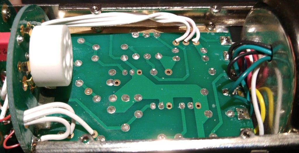
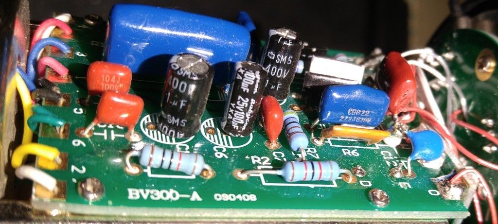
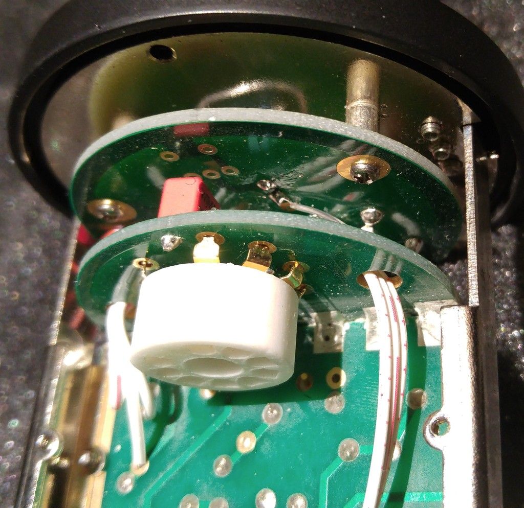
Here are some more pictures .....


Hope that helps shed some light on things. Thank you so much for your time!

ln76d said:
Ok, i think i have schematic.
90% sure it's same (before improvements).
Yes, microphone looks like used, and someone before made poor "improvements".
Pics of traces probably will confirm that.
In case of noise i would look for cold joints.
Even good capsule in bad circuit doesn't mean better effect ;)
 
ln76d said:
Last thing
Try to read value of that cap and see where it's connected.
Probably 1nF (1000pF) connected to pin2 of tube socket from one side but worth to check.
There's also few other options for mod, but this should be enough for now ;)
Good night.

If you are referring to the red cap it says 2.5 on one side and 220/630- on the other side. And it is a WIMA. And it is C11.  It seems to be connected to pin 6 on the socket via a trace on the bottom side of the PCB with the socket on it. Sadly you cant see the trace very well in this picture. I can try and check with my multimeter tomorrow.


Are you suggesting that I remove the caps or replace them with something better?
 
I forgot about one thing, if you would like to use "more advanced" modification there would be need to install extra resistor, let me know do you want to try it, then i will look how to simply do that.
Three caps which i marked are for remove only.
Some can argue with removing C2 (you can always put it back), but C9 and C10 makes really bad job in audible high frequency range. There's few caps which can be changed but for now you could try what i marked.
Step by step modification should give you some light on what is need to do.
Good 12AT7 should also make a huge difference. For CCDA circuit like this one i had really good results with Siemens tubes.
Another thing could be change of two cathode resistors - R7 and R8.
You could empirically set new values using potentiometers in its place - but about that also later.
For the Wima C11 check is it pin 6 or 7.
Here's how numbering looks from the pin side.
 

Attachments

  • ECC83_82_Socket[1].gif
    ECC83_82_Socket[1].gif
    4.5 KB · Views: 5
I can "get" the removing of the 100n RF-filter caps on the output, but... Why would you (want to) remove power filtering from the capsule bias?  ???

ln76d said:
Simple mod
 
ln76d said:
Some can argue with removing C2 (you can always put it back).

And here's the first one :D :D :D

Khron said:
Why would you (want to) remove power filtering from the capsule bias?  ???

There's completely no need to use 1uF value at this position.
I'm from those which like to reduce electrolytics inside microphones.
C3 will do necessary job here.
Also my next proposition would be R3/R4 change to 1M, so there definately wouldn't be any need to use 1uF electrolytic.
If there would be any noise issue (it will not) then here could be used 22nF-100nF film cap.
This is for next step ;)
That's why for now i'm for removing it.
 
I am going to try and get to work on this tonight. Wish me luck :)

The schematics are VERY helpful. I created a list of the values as best as I could get them off the M-Four to try and check that the circuit is indeed the same. I am working on following the connections. I thought I would share the values of all the capacitors as best as I could just in case it is helpful for anyone. 

C1 = 400v = 1uf
C2 = 400v = 1uf
C3 = CBB22 223j630v this one is hard to read so I am not sure on this one
C4 = H630 02j This one is unclear
C5 = 273J 630v = 0.027uf 630v  The TC-1 reads .022 630V
C6 = 100uf 25v Match
C7 = 104J 100v = 0.1uf 100v Match
C8 = 105J 250v = 1.0uf 250v Not Sure
C9 = 104J 100v Match
C10 = 104J 100v Match
C11 =  220/630 2.5
C12 = 27 3KV
 
I noticed the "BV300" marking on the PCB, and i had come across another topic here on GroupDIY a while ago, when researching details about the t.Bone Retro Tube II: http://groupdiy.com/index.php?topic=47042.0
 
I'm mildly curious about that too :p

One could argue they're slightly more prone to failure, with the relatively higher (read: warm) temperatures inside a tube microphone, and it has been shown that they can / do introduce some distortion when directly in the signal path, but...

I personally have no issue with using them in power supply filtering - although *only* if they're from one of the handful of reputable Japanese brands :p

The Sugar Lion said:
I am curious why you like to reduce electrolytics? What is undesirable about them?
 
Ha! So it looks like it wasn't modified by previous owner, just poorly made in factory :)
Yes it's the same as alctron.
Guys, i really have no time to write elaborates about "superiority" film capcitors over electrolytic capacitors.
There's so many places where you can find many usefull informations.
We can talk about capacitors distortions, esr, impedance, aging, tendency to failure bla, bla, bla.
In my opinion, best capacitor is no capacitor at all, but when is needed, then better is to use better capacitor ;)
As i said before, at backplate polarisation node 22nF is sufficient, if from any reason wouldn't be, there's possibility to add another film cap.
Why is used electrolytic 1uF at this position? Because it's cheap in manufacturing.
We have Nippon SMS 1uF here - wow, we have reputable manufaturer capacitor here, and there's another 1uF in the circuit.
But wait! It's only chinese fake capacitor, so i wouldn't keep it anyway ;)

The Sugar Lion - let me know do you want to make capsule connection changes from "advanced" mod schematic.
 
Khron said:
I personally have no issue with using them in power supply filtering - although *only* if they're from one of the handful of reputable Japanese brands :p

Khron - why you are using "*only* if they're from one of the handful of reputable Japanese brands"?
What gives you that? A sticker or better parameters or what?
If better parameters, then  typical cheap foil cap usual have most parameters (at least on the paper) better than any "reputable manufacturer" elctrolytic :p
 
Back
Top