Aurycle FET Mikes

GroupDIY Audio Forum

Help Support GroupDIY Audio Forum:

This site may earn a commission from merchant affiliate links, including eBay, Amazon, and others.
there it IS.

http://www.groupdiy.com/index.php?topic=47350.0

Cheers,
D
 
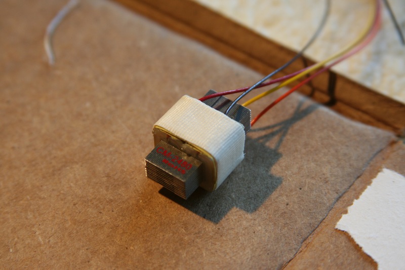
Very few updates, but I did get my Cinemag CM-2480's in and got a chance to work on the mike bodies.

The CM-2480's are GORGEOUS!  Very nice looking and appear to be very well made.

IMG_9993.JPG


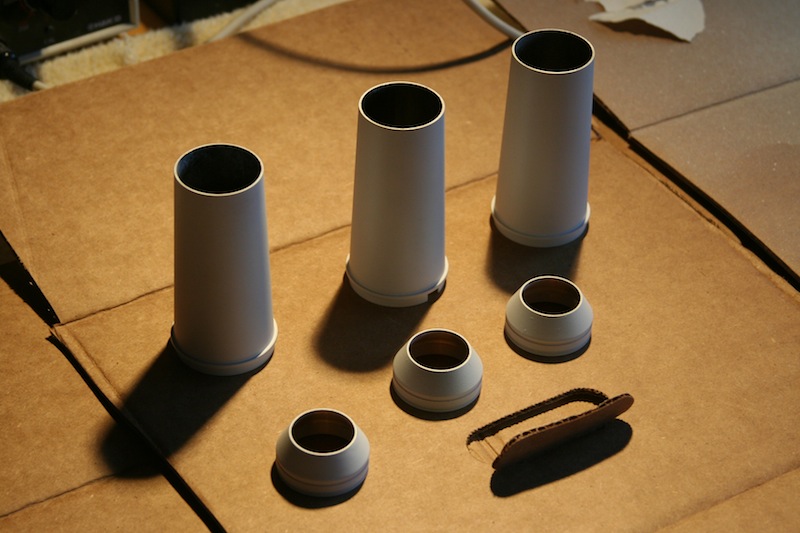
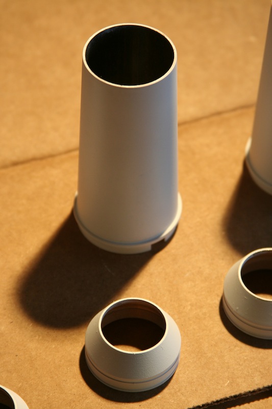
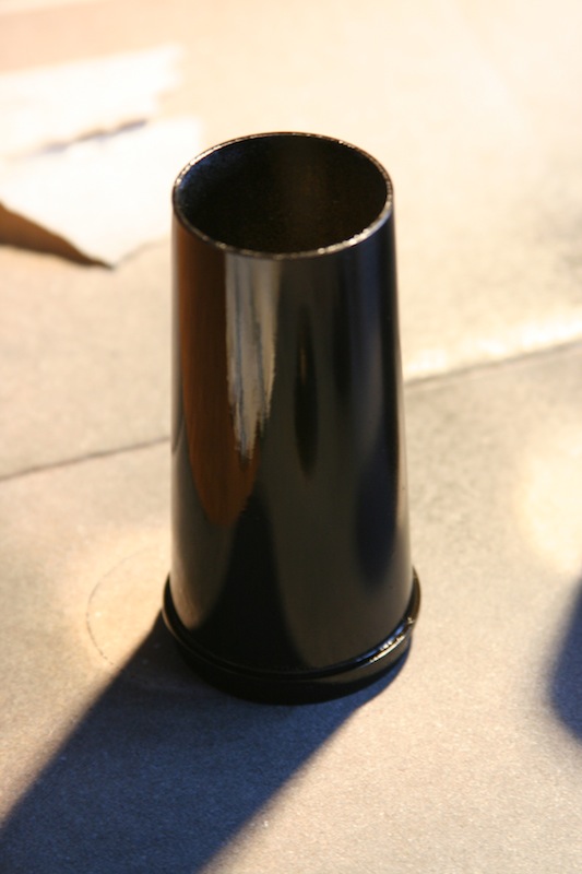
I did get a chance to shoot a coat of etching primer on all of the brass body parts:

IMG_9984.JPG


IMG_9985.JPG


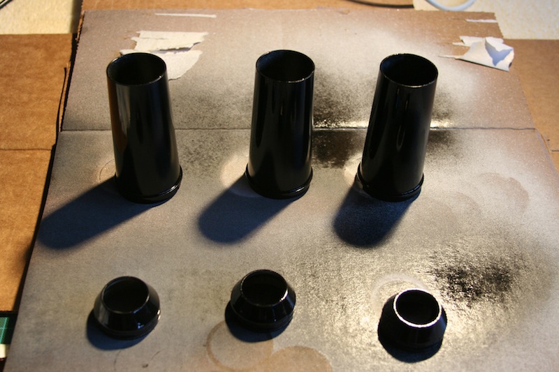
And then a coat of gloss black on the same parts:

IMG_9988.JPG


IMG_9992.JPG


The plan is I have some dry-transfer lettering that I'll put on after they are dry to show the name / capsule type as well as a simple graphic for the pad and high-pass switches.  Then I'll shoot on a few coats of satin clear to protect the lettering.

Then hopefully I'll get to solder some parts!
 
A few more pics and updates.

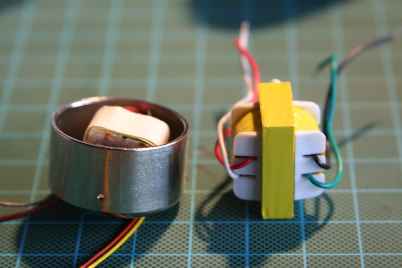
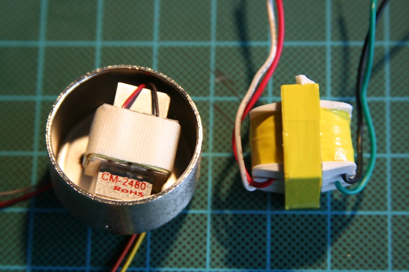
The CM-2480 finds its new home within the bell housing (with stock transformer next to it for comparison):

IMG_9996.JPG


IMG_9997.JPG


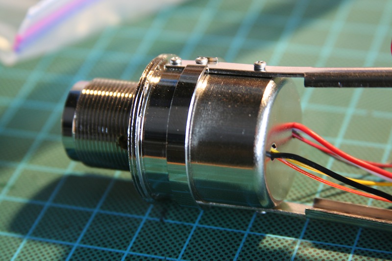
And gets bolted back into the frame:

IMG_9999.JPG


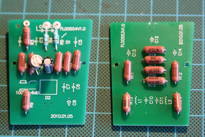
The two boards after the resistor stuffs.  I had a ton of 1/4W resistors to use up which are slightly larger than the layouts provide.  I believe a 1/8W resistor would fit perfectly.

IMG_0001.JPG


Notice that R6 (FET drain resistor) is replaced with a 5K pot so I can adjust the bias later.  I set it to 2.21k (regular value) as a starting point.

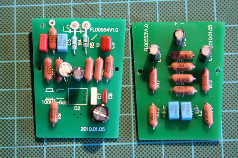
Boards after the caps and inductors are stuffed:

IMG_0004.JPG


As I said previously, biggest change is C8 which is changed from a 4.7uF tantalum to a 22uF bipolar electrolytic (large cap next to the bottom edge).

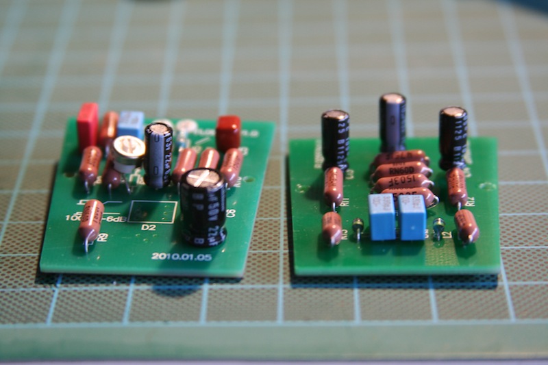
Another shot to show component height:

IMG_0005.JPG


The body has about 12mm clearance to the PCB so devices that are 12mm or less should fit without issue.

Next up is to install the JFET and PNP devices, then I can move on to wiring the HPF and pad switches and get the circuit boards back in the frame.
 
Matador said:
I did get a chance to shoot a coat of etching primer on all of the brass body parts:

And then a coat of gloss black on the same parts:
Make sure you have a method to electrically connect ALL the body parts (including the mesh) together and to earth.

This may mean scraping the paint and primer off certain locations.
 
Here is the biasing procedure (I finally got some scope shots).

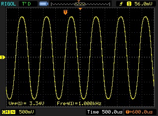
First, you set the adjustable source resistor (R7, or the source resistor that is in parallel with the bypass cap C4) to maximum resistance.  Then, with the capsule disconnected, you inject a test signal into the coupling cap leading to the gate of the JFET).

Here's a shot of the incoming signal (1kHz, 200mV peak-to-peak in this case).  The JFET device is a 2N3819 in this case.

bias_input.jpg


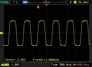
Then you set your scope to AC coupling, and place the scope probe on the drain of the JFET.  You then start increasing the input amplitude until one side of the signal begins to flatten out.  Here's what this looks like (you can see the top of the signal is starting to flatten):

bias_increase.jpg


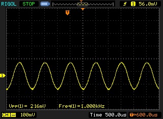
After this, you decrease the value of the source resistor until the signal again looks symmetrical:

bias_increase_after.jpg


You keep repeating this process (increase input amplitude until one side of the signal distorts, then decrease the source resistance until the waveform looks symmetrical), and after three or four iterations, you'll see that the waveform begins to clip evenly on both the top and bottom of the waveform as you increase the input amplitude.  Here's what this looks like:

bias_distort.jpg


This means you are done.

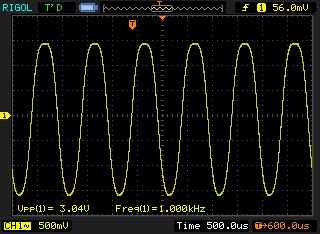
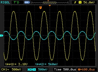
Here is the input and output signals:

bias_done.jpg


You can see with a 560mV input signal the circuit swings 3.18V, which is a gain of 6.  The theoretical gain is about 9 so this particular JFET is on the low side of the gain range.  I measured the drain DC voltage and it came out to 9.45V, and the other side of the drain resistor R8 which was 20.3V.  This means the quiescent current draw is roughly (20.3V - 9.45V) / 20K = 0.54mA.  All in all this seems like a good idling point.

To get my input signal, I tried the trick recommended here by using my DAW with a sine wave generator plug-in.  I made a cable with a 1/4" connector on one end, and a set of two alligator clips on the other end soldered directly to the braid and center conductor.  I could then clip the ground side to the mike chassis and the hot signal directly to the top of the 1G resistor.  Very neat and cost 0 dollars!

 
Is the quality of those cheap mic bodies, as good as the Neumann u87? Is the metal cheaper and thin or the-same? Does it have a cheap feel to it?
 
canidoit said:
Is the quality of those cheap mic bodies, as good as the Neumann u87? Is the metal cheaper and thin or the-same? Does it have a cheap feel to it?

I've never held a real Neumann, so I can't comment.  The Aurycle bodies however are solid brass and quite thick and heavy.  They certainly don't feel cheap by any means.

In fact I would say the bodies are the highest quality parts of these mikes:  the metal frames seem far cheaper and are just thin stamped metal straps with basic sheet metal screws.  However they are same as pretty much all the other Chinese clones out there.
 
Matador said:
canidoit said:
Is the quality of those cheap mic bodies, as good as the Neumann u87? Is the metal cheaper and thin or the-same? Does it have a cheap feel to it?

I've never held a real Neumann, so I can't comment.  The Aurycle bodies however are solid brass and quite thick and heavy.  They certainly don't feel cheap by any means.

In fact I would say the bodies are the highest quality parts of these mikes:  the metal frames seem far cheaper and are just thin stamped metal straps with basic sheet metal screws.  However they are same as pretty much all the other Chinese clones out there.
Would you say the quality of the body is comparable or even better than commercial mic bodies, such as Neumann, Bock, Flea, etc.
 
I have built a couple of these Aurycle mike kits and consider them great value for money.  Apart from a shock mount, which you can also get separately from them, they provide in the kit everything you need to make a mic that just plugs into an input and works. The Bodywork is great: any stains on the brass can easily be rubbed off with Brasso.  Even if you intend replacing the capsule and modifying the amplifier, these are a great bargain.  (I am sure it would take me ages to make a headbasket!)

David
 
For European,
you can find at musicstore (germany) a Fame mic wich is the same as the aurycle body for something like 40€. or 70€ with shockmount and case.
Cheaper since shipping from US is pretty expensive.

cheers.
Jr.
 
diyfanatic said:
For European,
you can find at musicstore (germany) a Fame mic wich is the same as the aurycle body for something like 40€. or 70€ with shockmount and case.
Cheaper since shipping from US is pretty expensive.

cheers.
Jr.

Hi Jr

which model is this?

thanks.
 
Looks like it is the C010
http://www.musicstore.de/de_DE/EUR/Pro-Audio/Mikrofone-Zubehoer/Fame-Studio-C010-Grossmembranmikro-Niere-Spinne/XLR-Kabel/Koffer/art-REC0001546-000

It doesn't have low cut / polar patter switches though. Great deal nevertheless with the case and all.
 
yep,

In my opinion the C05 and c010 share the same body as the Aurycle:

the C05 doesn' have the LC switch, nor the pad switch but it has shockmount include.
wich for a 42€ mic is a great deal

the C010 does have low cut switch (100Hz), no pad. but at 58€ it comes with shockmount, case and xlr cable. Unbeatable!

the C02 seems to be a different body (even from Aurycle mic), closest to the u87 head basket with LC and pad switch: 100€
it comes with shockmount, case and xlr cable. very attractive but I'm not sure it will make a huge difference of sound with the C010 head basket. but looks less "toy".

Musicstore shipping is 10€

the aurycle have low cut and pad switch and the price is 70$+40$ for europe shipping so it makes the mic at 82€ no shockmount, no case.
 
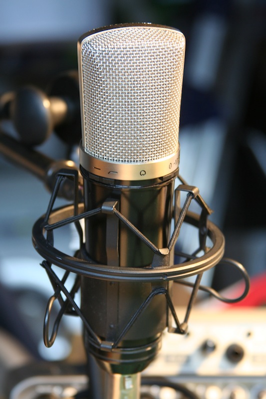
Here's a quick shot of the (nearly) completed mike:

mic_complete.JPG


I'm not entirely happy with how the finish turned out:  I found a local guy that does powder coating I'm considering having him sandblast the bodies and powder coating them black....
 

Latest posts

Back
Top