


buildafriend
Well-known member
Okay so I purchased 2 hairball 1176 rev F kit and I put them together. One I got working with the help of a good friend and the other has been sitting on the shelf since I cant seem to figure out why it's acting funky. I think it might be the output transformer.
1) Is it rare to get a bad output transformer?
2) If the signal seems to be going bad pre and post the transformer, is it safe to assume that my problem lies in transformer?
3) Are there any ways that I can test the transformer without putting my other 1176 at risk from desoldering and resoldering?
4) The output is about 1/3rd the volume of the functioning unit. It is also distorted.
5) Could this be a phase issue? ( that guess is a total shot in the dark )
6) Is it possible that I damaged the output xfrmr?
7) Do you think hairball would replace the xfrmr if I believed I received it in not working condition?
Here are some pictures of the signal pre and post the xfrmr to show exactly what is happening.
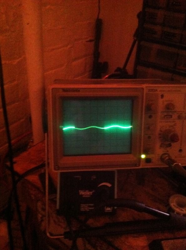
Oscilloscope scale is set to .1V per division at 5 milli seconds per division. Probe is set to 1x.
Test tone is approx 1v and 1K sine wave.
Pre xfrmr:
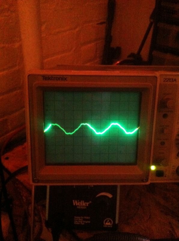
Post xfrmr:
1) Is it rare to get a bad output transformer?
2) If the signal seems to be going bad pre and post the transformer, is it safe to assume that my problem lies in transformer?
3) Are there any ways that I can test the transformer without putting my other 1176 at risk from desoldering and resoldering?
4) The output is about 1/3rd the volume of the functioning unit. It is also distorted.
5) Could this be a phase issue? ( that guess is a total shot in the dark )
6) Is it possible that I damaged the output xfrmr?
7) Do you think hairball would replace the xfrmr if I believed I received it in not working condition?
Here are some pictures of the signal pre and post the xfrmr to show exactly what is happening.
Oscilloscope scale is set to .1V per division at 5 milli seconds per division. Probe is set to 1x.
Test tone is approx 1v and 1K sine wave.
Pre xfrmr:
Post xfrmr:
")


![Soldering Iron Kit, 120W LED Digital Advanced Solder Iron Soldering Gun kit, 110V Welding Tools, Smart Temperature Control [356℉-932℉], Extra 5pcs Tips, Auto Sleep, Temp Calibration, Orange](https://m.media-amazon.com/images/I/51sFKu9SdeL._SL500_.jpg)


