Balanced Discrete Line Input

GroupDIY Audio Forum

Help Support GroupDIY Audio Forum:

This site may earn a commission from merchant affiliate links, including eBay, Amazon, and others.

Samuel Groner

Well-known member
Joined
Aug 19, 2004
Messages
2,940
Location
Zürich, Switzerland
Hi

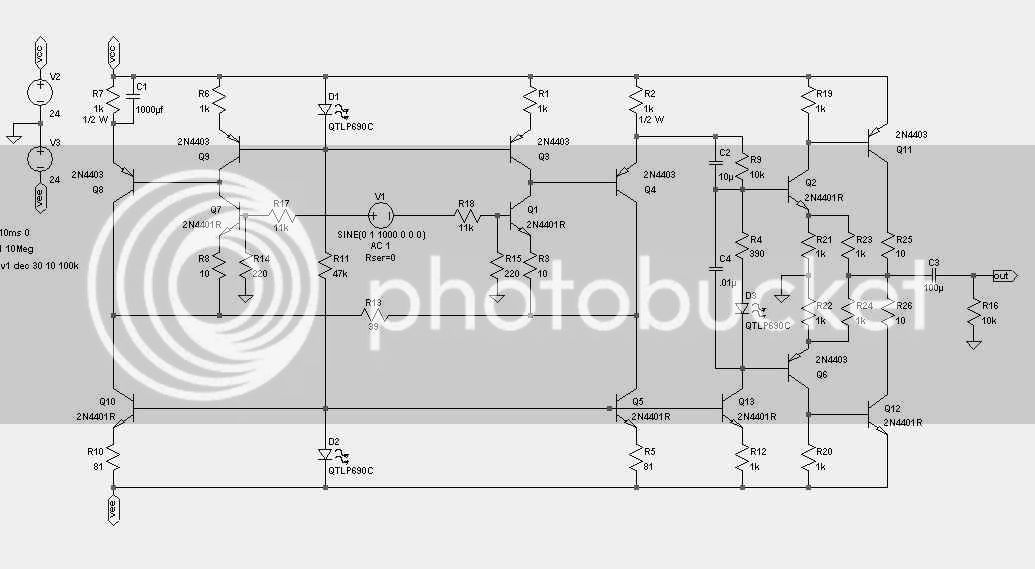
I'm currently working on a universal discrete balanced line receiver for EQs, compressors, summing boxes etc. My criterions were:
* good audio performance
* avoidance of the "Pin 1" problem
* reasonably high CMRR
* good RFI protection
* balanced input impedances
* class A output into 4k ohm up to clipping
* running on +/- 18 V, easy to adapt for other voltages
* easy to build (no semiconductor matching and selecting)
* cheap and easy to source parts

That's how it looks right now: [removed]

I decided against variable gain as this would have involved more elaborate circuitry. The CFP buffers in front are necessary to get balanced differential input impedances.

A question: Would Q301/Q302 benefit from clamping diodes or are D101/D102/... enough protection?

Any other suggestions and wishes welcome!

Samuel
 
[quote author="Samuel Groner"]
* good audio performance
* avoidance of the "Pin 1" problem
* reasonably high CMRR
* good RFI protection
* balanced input impedances
* class A output into 4k ohm up to clipping
* running on +/- 18 V, easy to adapt for other voltages
* easy to build (no semiconductor matching and selecting)
* cheap and easy to source parts
Samuel[/quote]

Samual,

This is fantastic. It states your goals and communicates them well. :thumb:
I wish more members posted like you do. Please keep them coming!!! :green:

Cheers,
Tamas
 
I love you too, man
icon_wink.gif

but I am what I am

Analag
 
It states your goals and communicates them well.
Thanks for the compliment! I think I learned that at university when getting tasks which do different...

I think thomas did already something like that...
Yes, I know that one. It does not meet my "balanced input impedance" criterion and I thought that I want some improvements i.e. on THD and slew rate.

Any opinion on the clamping diodes?

Samuel
 
I don't think the clamps are necessary, it takes a 16V swing on the input with no sign of clipping.
 
...a discrete mic pre, adapted for line input. Adjusted for unity gain; can drive 600ohms pretty well. CMRR sims out at only about 70dB, which might really be OK. Not a huge parts count.

discretelinein.jpg
 
[quote author="magicchord"]...a discrete mic pre, adapted for line input. Adjusted for unity gain; can drive 600ohms pretty well. CMRR sims out at only about 70dB, which might really be OK. Not a huge parts count.[/quote]
Interesting Av of 2 output stage. Have you gotten results on output quiescent current with temperature?
 
Naw, not yet. I want to breadboard it and see if it drifts.
I thought a AV=2 output stage would maximize headroom.
 
i dredged up this old thread because i have been thinking about the same topic more recently. in particular, i add these criteria:

typical gain of 1
possible gain of 0.5
assumed passive rf filtering in front
widest possible swing on input
assumed readily available transistors, with no matching outside batch buying
no ICs (there are plenty good ICs that do this whole function already!)

my reasoning is that this is the first stage. there is a good chance if you are EQing, compressing using a FET, etc that you want to knock the input level down a bit to maintain headroom, and add your gain back in the output driver. perhaps (assuming here that this circuit is substituting for an input transformer) that would be best achieved using a pad, but i'm wondering if operating this amp stage at a low gain could have some design advantages.

i assume this still would take the form of some kind of diff pair into a follower. with modern devices, operating at a low overall gain, i wonder if a VAS is strictly necessary, and if there could be a compelling advantage to omitting it.

since the input would be looking out into the outside world, presumably through a protective pair of input caps, it would be nice if there were low enough output dc offset to dc couple into the next stage. but that's a nicety rather than a necessity.

any ideas before i start jamming fragments together? is there a non-opamp like topology i should be considering?

ed
 
[quote author="Samuel Groner"]
That's how it looks right now: [removed]
[/quote]
Would be interesting to have a look at the original.

Thanks,

Peter
 
[quote author="edanderson"]no ICs (there are plenty good ICs that do this whole function already!)[/quote]

Since this is a nice & tidy thread with clearly stated design goals, shouldn't the reason for going discrete (i.s.o. ICs) be added as well ?
(partly serious, partly in jest)

So let's see how 'scientific' the strong unstoppable desire to have just a board with hot discretes i.s.o. one single IC could be formulated. :wink:
 
Interesting that this came up again as I started to think over it again (never did more work on the original schematic) just a few weeks back.

The general approach will depend heavily on the exact requirements:
* balanced differential-mode input impedance necessary or not?
* high (> 10k) common-mode input impedance necessary or not?

If both questions can be answered with no the possible answer is simply a differential amplifier. There are various means of changing gain then (e.g. balfig11.gif).

If only the second one is answerer with no I'd think about the "superbal" (balfig12.gif) or a fully differential amplifier (see e.g. aug_08.pdf for the basic idea of such an amplifier). Both configurations have the advantage of a balanced output but are not easy to modify for variable gain without CMRR or input impedance changes or another amplifier at the output.

If we have both questions answered with yes chances are you'll need a three-opamp instrumentation amplifier. A possible exeption is this: balfig13.gif. With a carefully designed input PAD it might be worth a try.

Would be interesting to have a look at the original.
It's not worth a look--a simple DOA configured as differential amplifier with a CFP buffer at each input.

Samuel
 
[quote author="Samuel Groner"]
If we have both questions answered with yes chances are you'll need a three-opamp instrumentation amplifier. A possible exeption is this: balfig13.gif. With a carefully designed input PAD it might be worth a try.[/quote]

interesting that this topology is not more common, considering that it requires only the usual two opamps and six resistors (plus associated feeback caps). for a gain of 1 this seems a solution worth investigating.

[quote author="Samuel Groner"]
[quote author="clintrubber"]Would be interesting to have a look at the original.[/quote]
It's not worth a look--a simple DOA configured as differential amplifier with a CFP buffer at each input.
[/quote]

i suppose you concluded that by the time you added 2 CFP buffers, you've almost got the same parts count as another DOA?

[quote author="clintrubber"]
So let's see how 'scientific' the strong unstoppable desire to have just a board with hot discretes i.s.o. one single IC could be formulated.
[/quote]

in my case it is more of a design exercise than anything. i don't expect that i can match the monolithic devices for matching related performance parameters. but the process of making something like this could teach me something. or not... but trying is the only way to find out. certainly there are many fine IC opamps, but that hasn't stopped anyone from using discrete opamps either.

ed
 
[quote author="edanderson"][quote author="clintrubber"]
So let's see how 'scientific' the strong unstoppable desire to have just a board with hot discretes i.s.o. one single IC could be formulated.
[/quote]

in my case it is more of a design exercise than anything. i don't expect that i can match the monolithic devices for matching related performance parameters. but the process of making something like this could teach me something. or not... but trying is the only way to find out. certainly there are many fine IC opamps, but that hasn't stopped anyone from using discrete opamps either.

ed[/quote]
These are of course more than valid reasons. :thumb:
 
[quote author="Samuel Groner"]
It's not worth a look--a simple DOA configured as differential amplifier with a CFP buffer at each input.
[/quote]

Which is possibly best solution in discrete world.
Maybe in IC world as well: http://www.thatcorp.com/1200desc.html

You could easily do discrete version of 1200 with 3 CFP buffers and DOA.
Or if you dont mind high Zdif as well, you could do with two buffers
with local bootstraping (and that would have better stability).

Key bottleneck in high performance diferential recievers are resistors
around diff amp. If you dont get 0.1% resistor network with good thermal
tracking you should simply settle to around 40dB CMRR and get
over with it . And 40 dB CMRR is not bad performance in real world
(in studio environment). High EMI resistance would be more
important design goal.

BTW unbalanced equipment with 50-100ohm output resistance is
not uncommon in studio. Plug that into "perfect" diff reciever with
10K Zin and your CMRR drops to 40dB

cheerz
ypow
 
Interesting that this topology is not more common, considering that it requires only the usual two opamps and six resistors (plus associated feeback caps). for a gain of 1 this seems a solution worth investigating.
Without PAD it does not get down to 0 dB--as shown it's 6 dB minimum. Furthermore CMRR will be worse than that of the standard 3 opamp instrumentation amplifier as the cold signals travels through one more opamp than the hot signal. Not a problem for audio but more often so in instrumentation.

I think I've seen more two-opamp instrumentation amplifier topologies but don't remember more right now.

Samuel
 

Latest posts

Back
Top