BC560 substitution...

GroupDIY Audio Forum

Help Support GroupDIY Audio Forum:

This site may earn a commission from merchant affiliate links, including eBay, Amazon, and others.

SaMpLeGoD

Well-known member
Joined
Jul 19, 2007
Messages
441
Location
Portugal
Hello,

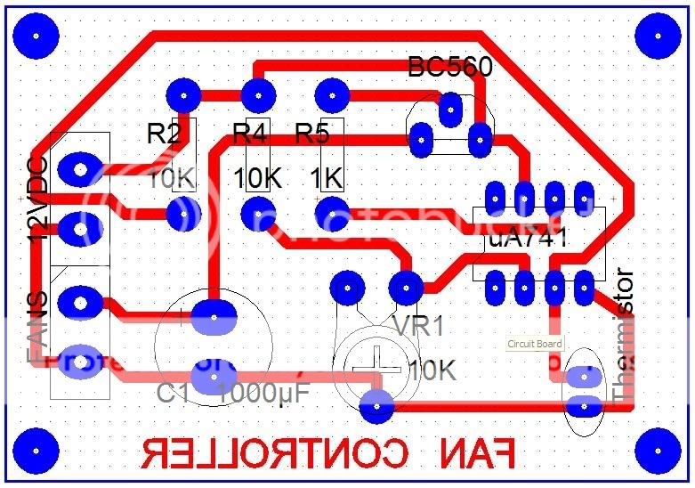
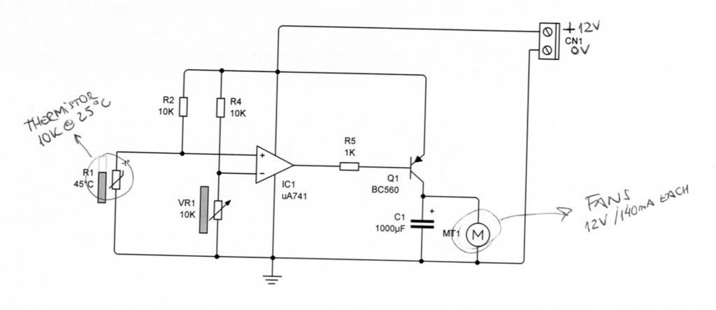
I just building an electronic temperature switch, that will make 2 fans start with the temperature rise...
The problem is that I use a BC560 that has a max collector voltage around 100ma... and need at least 280ma (140 + 140) to the fans...
How can I get another transistor with the BC560 same characteristics but with more collector voltage?
I'll post the schematic...

Cheers,

Eddie ;D
 
Hey Eddie,

I hope you meant collector current. this is measured in mA. For a sub for the bc560 try a look at the bc636, bc638 or bc640.

oliver
 
And put something like this on them http://www.rapidonline.com/Electronic-Components/Semiconductor-Hardware/Heatsink/TO-92-Heatsink/77178  ;D
 
Hello all... thanks for the quick reply!!
yes, I mean current inbstead os voltage, thought well, write wrong  :-\
Actually I already blow 2 of them with the heat... hehehehe
I'll try some of that you pointed above plus heatsink!
Thanks  lot one more time!!

Cheers,

Eddie ;D
 
Well, here is the schematic I used...

FanControler.jpg


comments? it works very well :)

Eddie
 
That's not a switch--I thought you'd just switch fans on and off, but what we have is rather a speed control. I'd just parallel BC560s (one for each fan), or use a power transistor in a TO-220 package (perhaps you should lower R5 to 100 Ohm then).

Samuel
 
Hi,
It looks to me that the circuit shows an adjustable temperature fan switch because the IC1 acts like a comparator.
However, I would suggest some changes:
- insert a 100k resistor between the IC's output and noninverting input in order to generate a small hysteresis,
- insert two signal diodes (1n4148 for example) in series with R5 (cathodes to IC output) to ensure that the output transistor is off when the IC's output is high,
- use three BC560 transistors conected in parallel for each fan, or any other medium power PNP transistor (1W, 0,5A), because a higher safety margin is required (fan's current draw usually increases in time),
- C1 may be lowered to a few uF.

Regards,
Milan 

P.S.
Below is the link to the (original?) shematic with explanations.

http://www.rason.org/Projects/fancont/fancont.htm

 
Hi! thanks for the link Milan! they use the 2N2907 instead of the BC560 but it has only 0.6A of colector's current... I think it's still very "tight" for what I want... maybe the BC461 or BC640 that they said above... a least it has 1A of Colector current...
The problem in improoving this is that I already etched the board... so I only have room for one transistor, and really  :-\
Here it is...

FanControllerBoard.jpg


So I think I'll take some of your mods, but will choose only one transistor to drive the Fans...
Just let me know what you think about it! Thanks!!!

Eddie ;D
 
That's just so wrong.....

> I already blow 2 of them

Of course. When the IC turns-on the transistor, "infinite" current flows to charge the 1,000uFd capacitor. Not infinite: u741 will put out a few dozen mA, times transistor gain, a couple Amps. Infinite-enough for little parts.

I don't really know why the cap is needed.

If you are going to drive a BIG capacitor, use a BIG transistor and put some resistance in there.

Also wrong: the u741 is not -sure- to drive the transistor OFF. And it could get stuck with medium current and full 12V voltage, which will melt little transistors. It should be done different. However a Darlington transistor will be less marginal.

Use TIP125 (TIP126 TIP127). It's fat. It's cheap.

index.php


Also wrong: it could be done with NPN which is a penny cheaper than PNP. (I remember when it was a dollar cheaper, and a dollar was big money.) But I won't design-out your penny.

> I already etched the board...

A good lesson. Breadboard it and do an extended smoke-test before you carve it in stone.

The TIP125 "can" be stuffed here. Put it diagonally so the TO220 B and C legs go in the TO-92 pinout holes. You may need to drill bigger. Now bend the E lead up. Tack the 3r3 resistor from E lead to E hole.
 

Attachments

  • Fan-cont.png
    Fan-cont.png
    7.6 KB
To add to PRRs post I would use a pullup resistor from the base to + 12.  This will help make sure the transistor is off until the opamp output  "pulls" the base to ground turning the transistor on.  You can do the math for the series out resistor and the pullup (100ohm series 10K pullup might be a good starting point).  I would get rid of C1 and install a flybackdiode across the motor.

It should use a comparator with hysteresis(like moamps post) not an opamp.

Like PRR posted "That's just so wrong....."
 
That's just so wrong.....

Ok... sorry about that  :-\
Just learning with my mistakes, I'm not an electronic pro, so far  :-\
I'll take all of your suggestions,  now it's clearer for me what's happening...
Thanks a lot :)
So I'm digging with TIP125 and 3R3... about the opamp... I used what I has hangging around, I'll change that to... any suggestion about that?

Eddie ;D
 
> I would use a pullup resistor from the base to + 12.

Might help.

The '741 specifications say that with +/-15V supply a 10K-to-ground load may only pull-up to to +12V, a 3V drop, so the transistor can "never" turn-off for-sure. "Typical" is 14v, which still is hopeless for a single transistor, though a Darlington will get awful quiet at 1V B-E.

The nominal schematic of u741 says that "saturated-up" is a current mirror and an emitter follower. The current mirror may not be as-shown, but if so then it can pull itself to 0.7V down from the rail. That will still leave a single junction part-on.

The pull-up resistor would have to suck-off any stray leakage from the '741's "up" condition, and drop less than 0.6V, yet not exceed the max-current in the pulled-down condition. 1K is safe "down", and 1K would pull-up 0.5mA, and '741's leakage is likely microamps. But who can be sure?

BTW: there IS a "pullup resistor" in the TIP Darlingtons. If you left the base open, it will pretty-sure go to low-low current, "nothing" in terms of typical TIP12x loads. Whether it is enough to suck-out "all" stray current from a jammed-high u741 is not clear.

It helps that in this case, nobody dies if the transistor won't stay OFF. Oh, a careless finger could get nicked, though a 12V 0.14A fan usually won't draw blood. Still, I don't like plans which may-or-may-not work.

Rather than hysteresis, I think it should have negative feedback so the fan speed rises with temperature. But with the high-gain Q1 stage, this would require more circuit changes.
 
Rather than hysteresis, I think it should have negative feedback so the fan speed rises with temperature. But with the high-gain Q1 stage, this would require more circuit changes

Well, It's a nice way to start a thread :) I'll use this Fan Controler in my PM670 since the tubes use to get really hot! I think maybe there's a lot of uses here in the forum for people that want to "cool down" their equipment ;) nothing better that a temperature's speed controled fan ;)

Cheers,
Eddie ;D
 
Hi Eddie,

If your PCB is already done, you may use some medium power transistors housed in the metal TO39 case,
such as the 2n4033, 2n3053, 2n2904, BC160,161 etc. The footprint of these transistors is very similar to the footprint
that you have designed for the output transistor so the implementation should be easy and straightforward. You may also wish to put a small "star-like" heatsink on the metal housing of the output transistor.
With the mods I suggested earlier, I believe your circuit will work well.

Rather than hysteresis, I think it should have negative feedback so the fan speed rises with temperature.

Hmmm...I'm not too crazy about the quoted solution - it has caused far too many computer crashes at my place of work. IMO, without a fan speed counter with feedback circuit and a fan failure alarm, it's like playing with fire.

Regards,
Milan
 
bc327 has the same case and 500mA of Ic and work fine in the circuit

Pier Paolo
 
moamps said:
IMO, without a fan speed counter with feedback circuit and a fan failure alarm, it's like playing with fire.

If you want to go fan control crazy:
http://www.maxim-ic.com/appnotes.cfm/an_pk/809/ Fig. 3 has a very simple speed control circuit. Works fine with 1/2 of a €0.07 LM358 in the opamp position and a real transistor (like BD139), if 10 V max. at the fan is OK.

One could probably connect D1 and R2 to a not-too-high-impedance 1:1 voltage divider instead of ground and connect the 10k+NTC voltage divider from your schematic (with the NTC and R positions swapped) to the +input, resulting in fan speed (not voltage) related to temperature.

The problem with simple fan voltage control is that it is impossible to run a fan reliably at slow speeds.  The circuit in the link can keep a standard PC fan at inaudible 200 rpm, which might be all that is needed in some situations.
 
Back
Top