Behringer ADA-8000 owners: PLEASE READ!!!

GroupDIY Audio Forum

Help Support GroupDIY Audio Forum:

This site may earn a commission from merchant affiliate links, including eBay, Amazon, and others.
I just found this topic again..

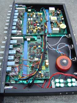
Since I powered up the unit the other day and it went belly up on me shortly thereafter.  Open primary just like Keith predicted.  I haven't been able to find a suitable replacement tranny so I might just swap the power supply stuff out with something like Keith's SSL9k powersupply and an added 5v regulator.
 
Svart,

I have a larger tranny with all the necessary windings... The SSL9K PSU almost certainly won't be able to supply the current without baking.

If you wanna tranny let me know. (multi-volt primary, all the right taps for the secondary, just too large to fit... de-mount it and you're good to go!)

Keith
 
I'd like to try it but I'd almost hate to take the tranny from you because I only plan on using this unit as an ADAT D/A.  I'm going to run this off of the lightpipe outputs from the Alphalink and use the ADA8000 outputs as 4 stereo stems for headphone pods so the folks in the studio can mix their own headphone mixes.  I'll only need the +/-15 and 5v(I think).

Does the unit really draw that much power or did they parallel the regulators because of the heat they had to dissipate?  Honestly I haven't even looked at it yet besides checking out the transformer after the thing went kaput.
 
I have a working one of these on the bench at the moment, running from 240V mains, which is reading 254VACRMS for these measurements. I've let it 'warm up' for about 30 minutes. This was under no external load (ie no input or outputs attached or signal going through it).

Secondary voltages are: 13.1VAC, 63.3VAC and 21.5VAC
DC into the regulators:
7805 5Vreg (IC1, IC2, IC7) = 15VDC in
7815 15Vreg (IC14) = +26.6VDC in
7915 -15Vreg (IC15) = -26.5VDC in

Temperature rise:
Ambient temperature is 22C, meaurements with the lid off (rise will probably be greater with the lid on).
IC7 temp = 66C (44C rise)
IC14 temp = 58C (36C rise)
IC15 temp = 58C (36C rise)
IC26 temp = 69C (47C rise)
IC27 temp = 69C (47C rise)

The transformer temperature rise was only a few degrees.

The electro supply caps used on the +/-15V regulators are cheap 470uF 35V caps. On this unit I measured ove 700mV ripple on them. They are also located between two hot regulator pairs. Using a low ESR 1000uF cap and keeping the regulators cool will help greatly.

I haven't had time to trace out a circuit of the PSU for component reference and there does not appear to be anything around on the net. Maybe I'll get to it before doing some mods to this one.

Geoff


SSLtech said:
The secondary AC voltage feeding the (7805) 5 volt regulators reads 11.2VRMS under load... That means that they are dissipating a LOT of heat... and there are three of them in parallel... right next to the main smoothing electrolytic cap.

The secondary AC voltage feeding the (7815/7915) 15 volt regulators reads 20VRMS under load per leg. The raw voltage going into each regulator is 27-point-something volts DC. They are dissipating a LOT of heat: certainly the heatsink is rather too hot to be comfortably touched.

The secondary AC voltage feeding the 48 volt regulators is 62VRMS. This is rectified up to about 80 volts.

Keith,
Have you measured the voltages which feed the regulators when running the unit on a 120vac line with the primary set to 230vac?
 
gswan said:
Keith,

What current measurements did you get for the rails? Do you have a sketch of the PSU circuit that you could share?

-Geoff

You should be able to infer the current readings under each condition using I=V/R... Right now it's at home and my workshop has a dozen other higher-priority things fighting for time and measurement...

I don't remember if I tried setting mine to 230V, but IIRC someone else did, and the numbers may have been just a touch low for happy regulation. line sag etc... (which would be a great pity!)

Anyhow, either way, the factory transformer just puts out TOO many volts!!!

Keith
 
SSLtech said:
I don't remember if I tried setting mine to 230V, but IIRC someone else did, and the numbers may have been just a touch low for happy regulation. line sag etc... (which would be a great pity!)

Anyhow, either way, the factory transformer just puts out TOO many volts!!!

Keith

I recently made some repairs to my Smart C2 (which I bought from Alan Smart his-self in 2000 while I was working on some records in England).  I brought it back to the US in 2001 and have used it on literally thousands of records since then.  I had it on my bench, upside down covers removed, poking around at voltages and suddenly wondered why the number "230" on the fuse block was upside down and "115" was right side up..."no way" I said aloud...  Ahem... I measured  12vDC out of the 7818 an 7918 regulators...  Holy CRAP!  10years of 'brown' sound! 

To be perfectly honest, apart from some very low level 60 and 180hz it sounded fine... NOW however, it runs WAY too hot...

What is it about these manufacturers running such high voltages into the regulators?
 
zmix said:
What is it about these manufacturers running such high voltages into the regulators?

It's not the manufacturer, it's the engineering behind it.

Let's say you have a 15V regulator and you need at least 17V into it to get it to regulate.

You need to be able to maintain the regulation under the worst case condition for the product to meet its specification.

The AC input line can vary by up to as much as +/-20% under normal operation. Add to that an additional 15% load regulation in a small, cheap toroid transformer.

So you need 17VDC in, using a bridge, requires 12VACrms from the transformer. Under the worst case conditions (80% mains voltage) this requires a 15VACrms rated transformer to give 12VACrms at -20% line voltage.

Under normal conditions this would give you 21VDC into the regulator if the transformer was heavily loaded. If the load was light and your line voltage high, you may have as much as 28VDC into the regulator.

This is why they are called regulators. They take a wildly varying input and maintain a constant voltage out. The difference between the input and output is dissipated as heat.
 
gswan said:
zmix said:
What is it about these manufacturers running such high voltages into the regulators?

It's not the manufacturer, it's the engineering behind it.

Let's say you have a 15V regulator and you need at least 17V into it to get it to regulate.

You need to be able to maintain the regulation under the worst case condition for the product to meet its specification.

The AC input line can vary by up to as much as +/-20% under normal operation. Add to that an additional 15% load regulation in a small, cheap toroid transformer.

So you need 17VDC in, using a bridge, requires 12VACrms from the transformer. Under the worst case conditions (80% mains voltage) this requires a 15VACrms rated transformer to give 12VACrms at -20% line voltage.

Under normal conditions this would give you 21VDC into the regulator if the transformer was heavily loaded. If the load was light and your line voltage high, you may have as much as 28VDC into the regulator.

This is why they are called regulators. They take a wildly varying input and maintain a constant voltage out. The difference between the input and output is dissipated as heat.

Perhaps I wasn't clear that I was being rhetorical in that statement, but I'm sure the punters will appreciate your clear and thorough walk through...

I've got hundreds of pieces of gear in my studio which use the 78xx and 79xx series regulators and also feature dual primaries on the mains, yet never reach the extremes seen in Keith's Behringers and my Smart stuff...

We typically see 125Vrms here in Manhattan. I wish that every piece had the flexibility of my 1966 Dolby A301, which has taps on the primary in increments of 5 volts.
 
I'm with you on that one. The ADA8000 transformer certainly has secondaries that are too high. It makes me wonder if the transformer manufacturers were trying to save a few dollars in copper by not putting enough turns on the primary. Even with worst case conditions we still see around 23VDC into the 78/7915 regs. Hmmm, I wonder if I could put some more turns on the primary :)
 
Using external transformer, to lower mains voltage (in my case by 50 volts, from 230V to 180V), works just fine. It's the simplest method. You can use one transformer to power several units with lower mains AC voltage. With 120V mains, as in your case, a 25V drop should be fine.

You can achieve that by 2x12V transformer, or 1x24V (I use 2x24V to get cca 48V drop from 230V), connect its secondary out of phase in series with mains. Each ADA8000 uses some 50W of power, so make sure that your step-down mains transformer is powerfull enough to feed all the units.
 
In a related story...

I've been using my 1984 SSL e series channel a LOT lately (rack mounted by http://www.proharmonic.com/  in Australia) . 
The power transformer is externally mounted in a small box but the PSU regulators for the + / - 18 and + 48v are inside the rack chassis.

I've had this thing sitting next to my mix position for a while and noticed that the chassis gets very very hot... you literally cannot touch the chassis near the regulators without burning your finger!  after reading this thread I decided to do something about it.  Step one was measuring the voltage at the secondaries...  ready for this? 56Vac with a center tap....  once rectified and filtered it's around 78V or 39Vdc feeding the 18v regulator...!    My quick and dirty solution was to wire the AC transformer for a 230v primary rather than 115v.  I am still able to get a well regulated +/- 15vdc out of the adjustable regulators, but the phantom is only able to produce 33v  (I don't care, I'll never use that).  Now it runs as cool as anything I've got...

Naturally the real solution would be to use a power transformer with a lower secondary voltage, and perhaps add a voltage multiplier for the phantom supply.

inside.jpg
rear.jpg

 
I just wanted to say thanks for this Keith ;D ;D ;D
This thread bubbled up to the surface maybe a month ago and I was reminded that I wanted to do this mod to my ADA 8000.  I followed the instructions and it took about an hour. the parts were probably 15 to 20 dollars and the mechanical part of the work was really simple.  Just need a little hot glue to keep the capacitors in place, but there's plenty of room.
My regulators are now seeing about 4 volts above regulation. the phantom was a bit higher and in fact my phantom on this unit is still kicking out at 53 volts, but that's unloaded.
Anyhow, I had it ON on the bench for a day and the case was no longer hot as f&*k.
I'm quite attached to this box, it's let me consider buying some really badass AD for mixdown, like a lavry or something It does such a nice job on the additional 8 channels I use for tracking and for feeding 8 channels of verb and delays and such.  I prefer my RME converters for my lead vocals and more transient-y stuff but the BERgers are really useful and I'm happy that it seems they aren't going to melt quite as quickly.
Kelly
 
zmix, just stumbled across this thread. That seems pretty wierd for the voltages you are getting on the SSL PSU. I  think something has gone astray, I certainly wouldn't have built it will such a high pre-reg supply voltage. It should be around 36Vac with a CT.
If you have the PSU apart again look at the specs on the side of the  transformer and see what the secondary voltages are labelled as.
Maybe a primary winding has shorted.

with regard to the ADA voltages all being too high, one simple thing to think about and crunch the numbers on, is to simply add a power resistor in series with the primary side of the transformer. This current protects the primary side of the transformer, and drops all the secondary voltages in one hit. Ballpark maths : say the transformer is pulling 20Watts, at 120 Vac that is 0.17 amps, say we want to drop all the secondary voltages by 30%, so we want 84Vac hitting the primary, thus if we put a 220R resistor in series with the primary we get pretty close. The resistor will be disapating around 6 Watts, so choose 10W metal panel mount one and away you go. You are tossing away heat, but at least the regs will be running cooler.

Rob
 
squib said:
zmix, just stumbled across this thread. That seems pretty wierd for the voltages you are getting on the SSL PSU.

Hi Rob,

Thanks for the reply.  I want to say how much i like this rack, it's simply ingenius that you were able to pull that off...  every tech here in NY has been stunned by the excellent workmanship.  THANK YOU!!! .. and can I get 7 more? :'(

I  think something has gone astray,
...and has nearly gone ashtray...! :eek:

I certainly wouldn't have built it will such a high pre-reg supply voltage. It should be around 36Vac with a CT.
If you have the PSU apart again look at the specs on the side of the  transformer and see what the secondary voltages are labelled as.
Maybe a primary winding has shorted.

The primary windings were paralleled to run at 115v, so a short isn't likely.  I connected them in series to drop the secondary voltages, so an open winding isn't likely either.

OK..... I've now opened the PSU case... looking at the label on the side transformer I can see the following markings:

30VA Toroidal Transformer
Clairtronic
Stock No.12015


Two primary windings, each marked "115v"

Two secondary windings, each marked "25v"

Considering that the line voltage here in Manhattan is a steady 125vac, each secondary will theoretically produce 27vac, which is very close to what I had measured (28v).

Seems that the transformer is OK, but the wrong type for the job.

How is the 48v supply generated on your custom PSU board in the rack chassis?  If it's straight off of the secondaries then swapping in a different transformer with a lower voltage secondary may be an issue. At the moment I am able to get 33vdc out of the phantom regulator, and a lot of modern condensor mics (akg 414, for example) will run from 9vdc up.

Here is the 30VA toroid transformer section of the Clairtronics specification PDF:
 

Attachments

  • Clairtronics Stock No.12015.jpg
    Clairtronics Stock No.12015.jpg
    16.3 KB · Views: 184
ooo

maybe i went mad that day. I'd guess that the phantom volts is derived from the doubler circuit and 25Vac primaries would be perfect for this. Revisiting it now it really wants dual 18V secondaries and then a tripler for the phantom. The old JLM PSU modules required a bit of a hack to get it to triple, the new ones have a link for double or triple.

So depending on how much this is an issue for you, a hack to the existing PSU module to get the tripler happening or a new JLM PSU built up with the link for a tripler and with either option a replacement 30VA 18Vac transformer.
The DC voltages out should be trimmed for +/- 18V

Rob
 
squib said:
ooo

maybe i went mad that day. I'd guess that the phantom volts is derived from the doubler circuit and 25Vac primaries would be perfect for this. Revisiting it now it really wants dual 18V secondaries and then a tripler for the phantom. The old JLM PSU modules required a bit of a hack to get it to triple, the new ones have a link for double or triple.

So depending on how much this is an issue for you, a hack to the existing PSU module to get the tripler happening or a new JLM PSU built up with the link for a tripler and with either option a replacement 30VA 18Vac transformer.
The DC voltages out should be trimmed for +/- 18V

Rob


Rob,

Mad? The entire project was a bit mad, eh?  What a creation!  What an incredible undertaking!  Hats off, to you , sir!

As for the exisiting supply... 79vDC after rectification and filtering is excessive even for a 48v supply...  and MAN did it run hot.... 8) 

If I need to have a full phantom I will start with a dual 18v secondary transformer and look at voltage doubling (or tripling).

  Can you please send me a schematic for the regulator board you used in the unit?  I'll see what I can get out of it.  The 611 cards in the SSL use local regulators to reduce the DC from the main PSU. Since this project is it's own universe, so to speak (incorporating only the mic pre, EQ and dynamics cards),  the global supplies are fine +/-15v.  Not so sure about your output driver though.. could I also get a schematic for that?

 
For 120V operation, why not put one of these ahead of the 120V input?

http://www.mouser.com/Search/ProductDetail.aspx?qs=atHKiefXm7SRpqo30qeT4g%3d%3d

Not perfect but expedient.
 
Back
Top