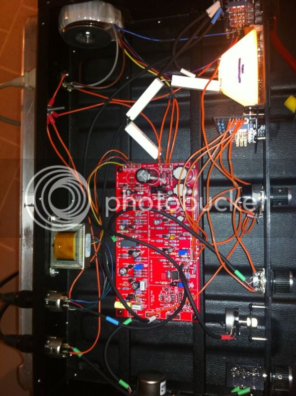
[BUILD] 1176 Rev F/G - new board, new transformer!

GroupDIY Audio Forum

Help Support GroupDIY Audio Forum:

This site may earn a commission from merchant affiliate links, including eBay, Amazon, and others.
svenandreen said:
Having some problems with calibrating my Hairball Rev F. When adjusting the Q BIAS I have followed the procedure in the mnats calibrationvideo:
feed the compressor with a 0dB  1 kHz sinus wave,
turn the Input knob full counter clockwise
turn the Output knob 3/4 full clockwise
set the attack to off,
the release to fully clockwise,
ratio to 20
and meter to +4.

The VU meter doesn't move until I turn the Output fully clockwise, and the Input about 1/4 clockwise.
If I turn both Input- and Output knobs fully clockwise and the Q BIAS trimmer fully counterclockwise, the VU meter reads only about - 8.
When I turn the Q BIAS trimmer fully clockwise the VU meter goes down to -20. I guess thats ok, but I'm wondering why I can't get the meter to read anything higher than -8...

Any clues? :)

Finally got it fixed. I had a broke transistor in Q5.  Now I just have to fix the GR metering...it doesn't show the right values...yet :)
 
Hi! This might be stupid question as I am really newbie in building audio stuff.
I made Rev A With mnats board  everything worked like charm.

I am building Rev F at the moment and I just finished PSU. The voltage readings are +29.7 and -9.7. Instead of 30 and -10.
How crucial is this???

Thanks already!
 
Fuzziator said:
Hi! This might be stupid question as I am really newbie in building audio stuff.
I made Rev A With mnats board  everything worked like charm.

I am building Rev F at the moment and I just finished PSU. The voltage readings are +29.7 and -9.7. Instead of 30 and -10.
How crucial is this???

Thanks already!

Those are great.  Anything within 5% is great.
 
Can someone help me track down the source of this crap?  :mad:

my negative CT hits star ground ( from my power transformer/toriod )

both of my XLR's on pin 1 hit ground

my IEC inlet is hitting ground

I dont get it.. why the hum


buildafriend said:
Can someone help me track down the source of this crap?  :mad:

my negative CT hits star ground ( from my power transformer/toriod )

both of my XLR's on pin 1 hit ground

my IEC inlet is hitting ground

I dont get it.. why the hum

Is this your own layout, or did you buy something from someone?
Is the power transformer talking to the output transformer?

-a
 
buildafriend said:
Can someone help me track down the source of this crap?  :mad:

my negative CT hits star ground ( from my power transformer/toriod )

both of my XLR's on pin 1 hit ground

my IEC inlet is hitting ground

I dont get it.. why the hum

Ground is a concept not a voltage.

That schematic shows multiple audio nodes labelled ground and that not likely to be the same clean voltage.

Hum is what you get when single ended circuits meet the reality of ground potential differences.

To troubleshoot you want to try to determine where hum is corrupting the audio. Probably easiest for work from the output backwards to the input.

With C15 lifted, is the output hum free? If not you may have hum coupling magnetically into the output transformer.  If clean, connect c15 and lift c10..
if clean connect c10 and lift C1

It looks like two alternate inputs but hopefully you see a pattern... Divide and conquer.

JR

 
Thanks JR!!!

I'll leave the input open with no test signal and just look for the hum through the circuit starting with the points that you have suggested.
 
Well if you don't lift the parts as I suggested it seems you could sniff for hum starting at the input and working through.  Problem with unbalanced, single ended circuits, how do you measure for hum? Relative to which local ground?

Good luck.

JR
 
Have you tried a seperate PSU, mounted off the main board? That's what worked for my 1176 hum troubles. It usually helps to have at least the rectifying diodes somewhere else.
 
a pic of inside the case may help as well, if you have long wires with lots of space between pairs you may be creating a hum magnet inside the case.  Are you using shielded cable on the in/out's?
 
http://soundcloud.com/dirty-old-women/memo-380/s-itBTK

That is the sound that I get without c15 in the circuit while the unit is powered on ( I dont think it being on would matter? )

Before I removed c15, it sounded like more a low freq hum. Now it sounds like a more of a buzz.. The sound sample above was just recorded on an iphone, it should execute the point.

6b4624dd.jpg

 
Hi,

I'm here http://mnats.net/1176_reva-d_hairball_wiring_attack_release.html

My question is about this step : Attach the other end of the shielded wire coming from the attack pot CW lug to the main PCB - shield to ground and the inner conductor to pad 7.

Can you tell me if I can solder the shield to INPUT ground ? Or somewhere else ? on Rev A there is 4 hole Ground / 7 / 29 / 28 but here only 3 hole 7 / 29 / 28

if you can help me for the output transformer... I really try to read the shematic, but I dont understand how to wire it... Ok for Brown / orange / red / yellow => in main PCB...
but what about Grey / Blue / Violet / green ???

AHhhhhhhhhhh ! I'm bad I know !

Thanks for help :)
 
The secondary goes to the output XLR pin 2 and 3 just like Rev A/D in the MNATs guide.  Look at the schematic for help with the colors.

 
Thanks ;)

I understand :

GRN and VIO twisted together + meter switch (X) => to XLR

BLU and GRY twisted together + meter switch (Y) => to XLR


Am I good with that ?
 
thanksa lot :)
and can you tell me where can I attach the other end of the shielded wire coming from the attack pot CW lug to the main PCB - shield to ground and the inner conductor to pad 7 ? where is the "ground" ?

:'(
 
germoju said:
thanksa lot :)
and can you tell me where can I attach the other end of the shielded wire coming from the attack pot CW lug to the main PCB - shield to ground and the inner conductor to pad 7 ? where is the "ground" ?

:'(

Have a look at the schematic and the board itself. Notice that the "F" has a different meter circuit than previous models.
 
Back
Top