


mnats said:germoju said:thanksa lot
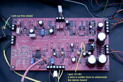
and can you tell me where can I attach the other end of the shielded wire coming from the attack pot CW lug to the main PCB - shield to ground and the inner conductor to pad 7 ? where is the "ground" ?
:'(
Have a look at the schematic and the board itself. Notice that the "F" has a different meter circuit than previous models.
")
is the answer : attach the other end of the wire coming from the attack pot CW lug to the main PCB - the inner conductor to pad 7, they is no shield ?
OR ? I put the shield wire in pad 28 ?


![Electronics Soldering Iron Kit, [Upgraded] Soldering Iron 110V 90W LCD Digital Portable Soldering Kit 180-480℃(356-896℉), Welding Tool with ON/OFF Switch, Auto-sleep, Thermostatic Design](https://m.media-amazon.com/images/I/41gRDnlyfJS._SL500_.jpg)


