[BUILD] 1176 Rev F/G - new board, new transformer!

GroupDIY Audio Forum

Help Support GroupDIY Audio Forum:

This site may earn a commission from merchant affiliate links, including eBay, Amazon, and others.
I had the 1176 Rev G in use at the weekend. I am using it in a live concert situation inserted into a vocal channel on a Midas XL4 console.

With a 4:1 ratio I have to keep the input pot very low (less than the 48 mark) in order to control the threshold. I expected to be able drive the input a bit harder say around 36 to 30 and use less output.

I have seen a few posts from others with the same observation and the suggestion of putting a 100 to 250k resistor in the GR circuit to reduce overall threshold.

The input to the 1176 from the console insert should be pretty standard  the console head amp is not running hot . It works ok with other compressors inserted DBX160x, DBX160vu etc

Could I have a problem with the gain of the input amp on the 1176 ?  or maybe an incorrect resistor value in the ratio ladder ?

David
 
Hi,

During the calibration test I found something strange.
When I enable the attack (bypass off) The vu is not showing the drop.
I tried many times with diifferents settings.... Everything else is working ...
Any tips where it could be coming from?

Thank's.
 
David RP said:
I had the 1176 Rev G in use at the weekend. I am using it in a live concert situation inserted into a vocal channel on a Midas XL4 console.

With a 4:1 ratio I have to keep the input pot very low (less than the 48 mark) in order to control the threshold. I expected to be able drive the input a bit harder say around 36 to 30 and use less output.

I have seen a few posts from others with the same observation and the suggestion of putting a 100 to 250k resistor in the GR circuit to reduce overall threshold.

The input to the 1176 from the console insert should be pretty standard  the console head amp is not running hot . It works ok with other compressors inserted DBX160x, DBX160vu etc

Could I have a problem with the gain of the input amp on the 1176 ?  or maybe an incorrect resistor value in the ratio ladder ?

David

I would triple check you bias adjustment.

You could also check your over all gain in bypass.  Should be about 40-45dB.

Mike
 
drask said:
Hi,

During the calibration test I found something strange.
When I enable the attack (bypass off) The vu is not showing the drop.
I tried many times with diifferents settings.... Everything else is working ...
Any tips where it could be coming from?

Thank's.

Your Qbias is set fine?

Double check wiring.
 
[/quote]

I would triple check you bias adjustment.

You could also check your over all gain in bypass.  Should be about 40-45dB.

Mike
[/quote]

Mike

Thanks. I re did the calibration and gain is about 42dB. Also double checked the resistor values on the ratio/threshold board. Still the same low threshold !!

I have gone down the resistor in series  with pad 22/C17  route and this has raised the base threshold to a more manageable level

David
 
There are two places where it is requested to use a two strand shielded wire in which you are only really using one conductor. I noticed on the PCB that the ground that you are soldering to doesn't actually connect to anything.  This is my first Build and I'm just wondering if that blank ground is going to make any difference if I just don't use it? I am specifically talking about the shielded wire that is connected to the clockwise lug of the attack pot, then attach the other end of the shielded wire coming from the attack pot CW lug to the main PCB - shield to ground and the inner conductor to pad 7.
 
Here is another 1176 Rev F,  this time in the AE special edition look.

I've rewired the switch on the attack pot to add an additional 150nF timing cap in series to the stock 22nF value to give me an extra slow release time in the "off" position instead of having the "GR off" function.

I find the REV F to be the most subtle of all the revisions A / D / F.

17g475.jpg
 
Hey folks!

I built a few rev F's a few years ago and they are still working great. So, I built one for a friend but I am getting a strange reaction. I have no signal on either side of the output pot but the wiper of the output pot shows what you see below. the voltages in the gain reduction section and meter driver section seem to match my good working one..

It does pass signal nicely when the compression is in bypass.. nice clean input and output gain. 
-JP

( the image uploaded sideways )
 

Attachments

  • photo.JPG
    photo.JPG
    53.5 KB
buildafriend said:
Hey folks!

I built a few rev F's a few years ago and they are still working great. So, I built one for a friend but I am getting a strange reaction. I have no signal on either side of the output pot but the wiper of the output pot shows what you see below. the voltages in the gain reduction section and meter driver section seem to match my good working one..

It does pass signal nicely when the compression is in bypass.. nice clean input and output gain. 
-JP

( the image uploaded sideways )

Is the GR FET socketed? Can you remove it from circuit?

How did the calibration go?
 
Just reviewing components for a rev f/g that I'm building and I see a few things that are apparently missing.

This is a complete kit bundle from hairball.

Resistors:
R18  22k  - there was no 22k res in the kit, but there was an 18k included that is extra - can't remember if that's a replacement for the 22k or not?

R49  4.3k  - was not in the kit, but I see someone at hair ball had crossed it off the printed parts list that was included ?

Finally, the R5  10M ratio resistor - I don't think I have ever omitted it, but on the parts list hairball notes "omit or 10M".  Since I didn't get a 10M is it now standard to omit it?  I assume it does not require a jumper since I was not mentioned?

Thanks!
Don 

 
The 10Meg being omitted was addressed in posts 36 and 37. You can leave it out.

Those other two should be as per schematic/BOM though.
 
germoju said:
As I was desperate I decided to plug my rev F without shield from the wire of the attack pot connected to main board pad 7. I try to power it and it works, first victory... but tests points indicate +21,8V (too low !) and the other -9,6V (good I think).
Nothing's burning or too hot...
I try to send some sound and sound's good... so I calibrated it and it worked perfectly !
So I got a rev F with good sound, good calibration, good compression but with only +21,8V at test point => ??

please where can I find a shematic with typical voltage ?

germoju, I know it's been a LONG time, but looking at your photo's you have VR1 in the power supply in backwards, which is  very likely what is causing your voltage to be off.
Posting in case someone looks at your photo and does the same thing.

Cheers! 
 
Hi all,

I am trying to wrap up this F revision 1176 and am having problems with my -10v rail. The Q bias trimmer is affecting the rail voltage. When the trimmer is removed i get a good -10v but when I put it in my voltage drops to -5 to 6 volts. Adjusting the trimmer actually changes my -10v rail. `I can clearly see that it is connected correctly and I also replaced it to be sure.  What am I missing?

 
Hi All.

I'm having an issue completing the meter tracking calibration on a unit here.

As per mnats video - I am able to set up the compressor for a 10db drop when toggling between GR on/off in VU.

The problem is that when it comes to adjusting the meter tracking trimmer in GR mode -  I run out of adjustment on the trimmer before I can get the meter to read -10.

I've tried changing the trimmer from the default value to 500k (same value as the G1176) but it hasn't made any difference.

Any ideas ?

Cheers
 
Hi
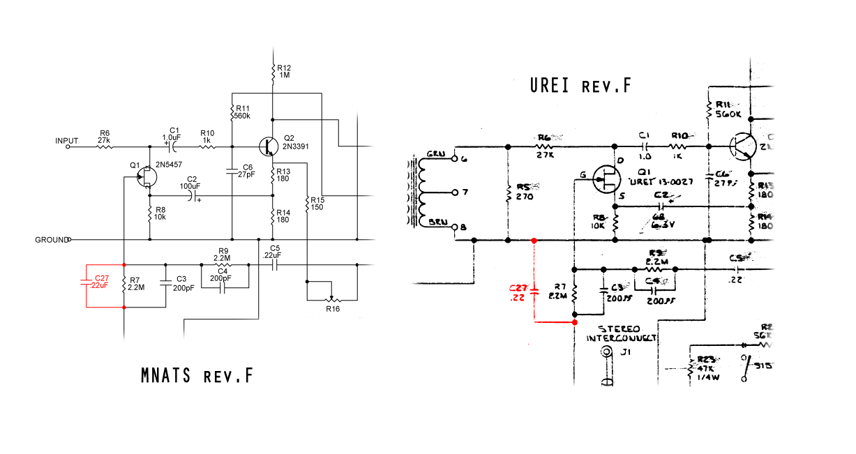
I think in the Mnats schematics( I don't know if also on the PCB) there is an error
C27- .22uf  is in parallel to R7 2M2
In the real schematics C27 is connected one side to R7 and one side to ground.
I'm not an expert but could be this the calibration problem?
::)
 
ilfungo said:
Hi
I think in the Mnats schematics( I don't know if also on the PCB) there is an error
C27- .22uf  is in parallel to R7 2M2
In the real schematics C27 is connected one side to R7 and one side to ground.
I'm not an expert but could be this the calibration problem?
::)

i already reported this to Mike about a year ago, here is his answer:
Hairball Audio said:
Mike,

tho i know this is a rev.A thread, i meant this difference:
1176_rev_F_c27_question.png


is this intentional?

thanks


Look at the PCB.  I think it's just an error on the schematic.

Mike
 
Olegarich said:
Is there any onfo  on "Wiring revision F"? I can't find on Mnats and in Hairball Audio (Only rev A and D) web pages.

Should be wired the same. Just use a 100K on the output rather than a 250K.

Mike
 
Olegarich said:
Is there any onfo  on "Wiring revision F"? I can't find on Mnats and in Hairball Audio (Only rev A and D) web pages.
My pages are titled "Wiring the Rev A/D/F with a Hairball Case". There are differences with the output transformer but these are marked on the main PCB; the secondary is a matter of connecting blue and gray as the hot side and the remaining two as cold.
 
Back
Top