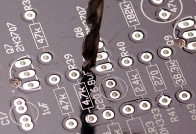
I've edited this post after calming down and figuring out the obvious and easiest way to fix my prefabricated boards.
The top plated-through pads really do nothing on most of the components, save for the ones that attach to the ground plane. The error as discovered above is that an extra pad I added to the board in four places is attached to the ground plane rather than isolated from it.
Solution: remove the top pad. Method: use a normal twist drill and gently remove the offending pads as pictured above. You can just twist the drill between your fingers. The copper pads are fairly soft and should come off after just a few turns.
You can still use this hole to mount the 2N5088 substitution after modification and, of course, the board will now work properly with a 2N3707/8 in the main footprint as well.
Archived, more complicated solutions below. See the images to identify the pads that need to be modified:
[quote author="mnats"]Here are two possible ways to solve the problem of my stupid mistake. The first one involves cutting the tracks on the back (non-silkscreen) side of the board. Do this if you are going to use the 2N3707/8 footprints.
The second solution will work for either the 2N3707/8 or the 2N5088 footprints and involves cutting around the offending pads themselves on the top (silkscreen) side. The 2N5088 uses the extra transistor Base pad that has caused all the misery ;^(
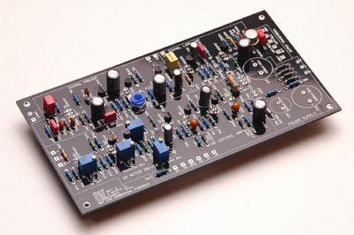
Here is the partially stuffed board. You can click on most of these pics to enlarge them.
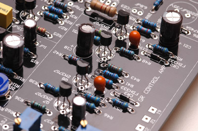
This is the section we are going to work on - the Gain Reduction Control Amplifier. Note that Q7 through Q10 have a single round pad near the oval ones. This is the Base pad that you would use if you are going to put a 2N5088 transistor or similar into the GR Control Amp. Otherwise for the 2N3707/8 you would just use the pads I have used in the example.
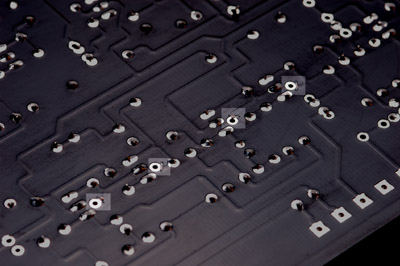
Flip the board over and cut the tracks leading to each of the base pads as highlighted in this image. You can use a small hobby knife or whatever - just make sure you
only cut the tracks that go to the small round pads shown.
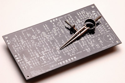
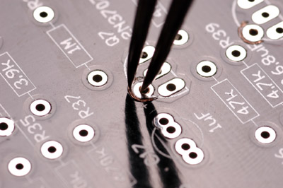
The second solution is more elegant and I think even easier to do. It is also the better solution as you get to use either transistor footprint as was originally intended. Get a pair of dividers and make sure one point is nice and sharp.
Drop the duller of the two points into each round Base pad and run them in a semi-circle around the half of the pad that faces away from the transistor footprint. Do this for all four Base pads in the GR Control Amp section.
After doing either mod, test for continuity. Note that with the first mod, the unused Base pad is still connected to Ground, but the rest of the circuit should now be separated. In the second mod, the Base pad will test open to ground.[/quote]
does this track cut fix the shorted resistor or another one?
Yes! The shorted resistor you found will be fixed as will the other three shorts.
I'm not sure I knew about the marginal spec on the 2n3707s
I can't force anyone to read my Rev D page but I would suggest reading it if you are joining in on this project. It is linked from the first post of this thread and my Rev D board sales thread. Make sure you check all the Lab threads I've linked from my page too. I'll try to add to this page as I have time to make any additions or corrections that we find along the way.
Again, many apologies for the error on the boards. If anyone feels they can't handle these mods, feel free to send your boards to me (address on the back of the packet) and I'll fix them and send them back to you.
I believe that anyone who cannot do the new modification at the top of this post should probably not tackle this project anyway. All boards I send out after today will be fixed before they are sent. Thanks to strangeandbouncy for finding this problem before we all went crazy trying to find the fault.
