build a better constant current load

GroupDIY Audio Forum

Help Support GroupDIY Audio Forum:

This site may earn a commission from merchant affiliate links, including eBay, Amazon, and others.

manaduar

New member
Joined
Mar 13, 2014
Messages
4
Hello,

I'm not an electrical engineer and or have a background in electronics, although I am an IT professional by trade.  I have taken on an assignment to help contribute to a PC hardware review website who is in need of somebody to review PC power supplies.  I began looking into the hardware that would be needed to do the testing and saw the price tags... :(

An oscilloscope I don't think I'm going to be able to get away from having to purchase, but while looking around for different options to generate a load to test with, I found the youtube video by dave jones:

https://www.youtube.com/watch?v=8xX2SVcItOA

a little more looking around and I find out everybody and their dog apparently has seen this video and knows about it.  I'd like to build something like this but I had a lot of problems to start:
1.  I wasn't sure he was speaking english (I'm not refering to his accent)
2.  I needed something that could be adjustable from 10% to 100% load of any PC power supply out there
3.  it would need to be able to test a single or multiple rails
4.  it would have to be able to evenly distribute the load across 3.3v, 5v, and 12v power.

PC power supplies ( I'm sure anybody on here would understand this but I'm trying to be thorough in my explanation) can range anywhere from 250W to 1500W+ giving over 70 amps on a single connection, so this would take a LOT of load which.  Dave's load, as he states in the video can only draw 1 or 2 amps.

I've been reading up on op-amps and mosfets since those were his two main components and trying to learn how this works so I could try to figure out how to scale up and I had an idea.  Instead of trying to make a single load scale up to 1500+W, just scale up, lets say 10 or 20 amp draw and build multiples so that I can adjust each one of them individually.  I'm still studying but I got to a point where I needed to try some hands on to better understand.  At this point I haven't gotten to building multiples.....I haven't even gotten to building a single one.  I'm stuck in a position where I THINK I understand how an op-amp should work, but I'm experimenting and not getting the results I expect.  So I'm looking for some help understanding.

I went to radio shack and bought some supplies to start experimenting, here's what I've got on hand:
breadboard w/jumpers
wire
solder
soldering iron
cheap multi-meter (which apparently can't read milli-amps)  :mad:
1/4 watt variety pack of resisters from 10ohm to 1m ohm
300 degree 100k ohm potentiometer
15 turn 10k potentiometer
8 9V batteries
automotive battery charger (sounds funny I know, but I can get 2A, 10, or 50A at 12V so I thought it might be a good test considering the power I intend to be drawing later and the mosfets I have on hand)
LM741 op-amp
LM324 quad op-am
three 20N60c3 mosfets (I had an old just PC power supply that I decided to cannibalize and found some of these mosfets in it, I looked up their data sheet and they are 600V 20A)


I realize how janky and noob this sounds, but as I mentioned, I'm not an electrical engineer so tools and supplies in this area are not a common part of my repertoire.  I need to minimize my expenditure as I am recently unemployed, I don't know when I will be back to work, and this is all in an effort to make extra money to hold me over until I'm employed again.

For the time being, the first problem I'm having is with getting the expected results from an op-amp.  I've tried numerous variations to attempt to get some sort of effect but I've had no luck and even what SHOULD be the most simple test is failing

300px-Op-Amp_Inverting_Amplifier.svg.png


the setup:

V+ connects to positive post of 9V battery
Vout connects to 10 ohm resistor
V- is connected between 10 ohm and 100 ohm resistor
100 ohm connects to negative post of 9v battery

2 9v connected in series, positive post of batt A connects to Vh of op-amp, negative post of batt A to positive post of batt B and negative post of batt B to Vl.

my understanding is this: Vout = Vin(1+(R1/R2)) in this case R1 is 10, R2 is 100 and Vin=9, so I SHOULD see 9.9V but I'm actually getting values in the 8.?? range.  I've already been experimenting so my batteries are already not at 100%, and I know there's going to be some amount of V-drop going through the components but I don't know how much I should see or how accurate my reading should be.  So in order for a more extreme example so that I should see a large enough result to overcome any loss in voltage I swap the resisters so that R1 is 100 and R2 is 10.  When I do the math on that I get 9(1 + (100/10)), 9(1+10), 9(11), = 99 volts.  I realize that Vout can't exceed Vh, which should be 18V.  when I test this out I get something in the neighborhood of 8V again........ ???

I've been trying to find an answer and so far the only thing I've found that might be related was on this forum.  There was a post were somebody was talking about wiring a 9V battery backward and that started me thinking about a V+/V- compared to a V+/ground.  I'm still looking for answers but after two weeks of reading I could really use people to ask questions and get advise from.  does this "backward battery" issue somehow relate to why I'm not getting the expected outcome?  just getting this much answered would be extremely helpful.
 
manaduar said:
Hello,

I'm not an electrical engineer and or have a background in electronics, although I am an IT professional by trade.  I have taken on an assignment to help contribute to a PC hardware review website who is in need of somebody to review PC power supplies.  I began looking into the hardware that would be needed to do the testing and saw the price tags... :(

If you don't have an EE background, with some specialization in high-power switching power supplies, I respectfully suggest that you recuse yourself from this assignment.

Not the least of your concerns is that testing these things is potentially lethal.

-a
 
No, no EE background, but I have had enough education and experience in electricity over the years that there's some "common sense" that I think could keep me......alive
 
I don't believe an EE degree, alone, will be of any use here.

I've worked with too many Senior and Masters EE students who could compose complex experiments and elegant equations, but could not compute a voltage-divider or low-pass on the bench.

PC power supplies is a real sub-sub genre of the whole EE field, so the EE courses alone don't give the specific insights you need.

In bygone days an EE student came to campus with a couple years of blowing-up (sometimes fixing) broadcast and ham radios. That IS useful.

The EE graduate gets a job and that's where the REAL learning happens. Blowing-up stuff under direction of a more experienced and goal-directed project leader.

> getting the expected results from an op-amp

I had a headache before I read this passage. It's worse now. Maybe I'm overlooking an obvious? But it isn't clear WHAT you have done.

The EE school would (or did?) teach you to use the CHALK-BOARD. You really can NOT talk efficiently about circuits without at least a crayon. Text descriptions are NOT efficient. And while you may not care about your time-efficiency, when asking for help, you need to "make it stupid simple" for the people you are asking.

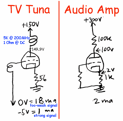
I'm not fond of Drawing Programs. Wrassling the tool distracts from getting your idea down on paper/pixels. I like crayon/pencil. For Cyber-Space, a scanner and a tool to get appropriate size and contrast and legible annotations. Like this:

fiTSWQZ.gif


Yeah the lines are crooked. But the what-connects-to-what is fairly clear. (To critique myself: it isn't clear that the "+300V" and the ground-scribble are two ends of one power supply. In tube-work this is conventional; it wouldn't be to someone coming from op-amps. And the original post was larger less fuzzy so the small print was clear; I downsize here for space.)

> Vout connects to 10 ohm resistor
> V- is connected between 10 ohm and 100 ohm resistor
> 100 ohm connects to negative post of 9v battery


I still can't work this out.

However "Vout connects to 10 ohm" freaks me out. Do you expect a '741/'324 to drive a 10 ohm resistor?? What is the maximum Output Current of these chips? (Hint for looking-up: bet on 10mA, but often 30mA-40mA.) What is the voltage they can force in a 10 ohm resistor? 10r*10mA= 100mV = 0.1V. (Often 0.3V.)

Generic op-amp chips can drive 2K load. Not 10 Ohms.

But then you say "I SHOULD see 9.9V but I'm actually getting values in the 8.?? range."

Nevermind the EE degree. Basic Philosophy teaches that you never get out more than you put in, and you usually get less than that. So how would you think "SHOULD see 9.9V" when you only have a 9V supply?

Or have you stacked two 9V supplies?

If so, where are the inputs sitting?

"...getting values in the 8.?? range."

Be Specific!! Does not hurt to read "8.92V" or "8.53V".

Particularly when it may Matter. In transistor chips, "get less than you put in" often comes in 0.6V lumps. And there's often two transistors between the output and the battery. So if you had reported "8.7V" I/we might say "Ah-ha! Two of 0.6V drops plus a bit of internal resistance.

> my batteries are already not at 100%

Which means WHAT? 9.1V? (A fresh 9V batt reads over 9.0V.) Or 8.1V? Or 3.21V? You MUST keep a sharp eye on battery voltage. Otherwise you spend a day debugging a pedal that works fine with a non-dead battery. As a fledgling power supply tester, testing supply voltage should be obsessive. When bringing-up vacuum tube amps I often have more meters on the supplies than in the circuit.

I *encourage* your learning. But pose questions in the form of pictures.

I would hope to *discourage* you posting reviews. There's already WAY too much dumb crap on the Web.

Side-notes: you can test a power supply with a resistor. Put a 1 Ohm resistor on a "5V" output. What is the current? (What is the dissipation??) And this goes with your "modular" idea: I've used one to twenty 68r resistors to test a 6V supply from small to large current. (A box of 68r resistors fell off a truck.)

But the output is never perfect. Is 5uV ripple acceptable? How about 50mV? Does it matter if the ripple is 60Hz, 360Hz, or 56KHz?

PCs offer special problems. They jiggle 4 _Billion_ times a second. All interesting CPUs will turn large sections off and on as-needed (if doing all integers, don't need the floating-point unit; if running tight loops the RAM manager can rest). So you should have a test-load which can simulate FAST change of load, and enough meter/'scope to know if it bobs or wobbles or spikes.

And as a too-practical point: "all" good PC power supplies will very-nearly meet their specs, and any over-sell is covered by encouraging buyers to go "large". Yes, there are "bad" PC power supplies that don't meet spec (or 'do', but die in 31 days). Review Sites will normally be looking for Free (Evaluation) Samples and also ADS. The not-good PC part makers don't do samples or ads. So the stuff you will be reviewing WILL be all "GOOD". Your review can be based on the shine of the chrome, the number and length of leads, the fan sound (both loafing and grinding out the kills). This is no less honest than the newspaper car reviews which comment on the seats and the radio but make no effort to verify Horsepower.
 
PRR:

thank you for at least an attempt to be informative, I'm going to reply to some of your comments, then try to be more clear in showing my setup and asking my questions.

in terms of the power supply reviews, it's not as simple as "if the manufacturer is willing to send you one, it must meet standards"

for average consumers, yes, just read the box and pick up whatever suits your needs, going out and reading PSU reviews is just a waste of time.  But the average consumer buys Box PC's from Dell or HP and doesn't normally shop individual components.  review sites are generally geared toward PC enthusiasts that prefer to build their own rig and will be selective about their parts, trying to get optimal performance.  going "large" is of course something all companies will encourage (since the bigger the more profit is usually the case), but an enthusiast building a gaming rig will know the power requirements of his individual compontents and try to meet them AND have room for future expansion.  For example, how many watts would a 2 dual GPU R290x's, an intel 4770, 2 PCIe SSD drives in raid1, a 5tb secondary drive, a dozen 120mm fans, and all the miscellaneous components take at idle?  What about running the most demanding game?  would it be more watts than the budget PC from Dell?  what if they overclock?  what if they have the PC for 6 months and a newer, faster video card comes out that requires 50 additional watts, and they want to swap out both of their video cards for two of the new ones?

in terms of power, enthusiasts are going to pay attention.  ripple is of particular concern for overclockers because they are raising their signal threshold closer to the voltage max, leaving a smaller margin of error for variances between each cycle, so if ripple causes a dip that correlates to a signal peak, thereby causing it to come in under the threshold then that's a problem.  And of course there's going to be the info that you analogized to car reviews talking about seats and trims, which isn't technical and doesn't look at performance, but for some people that is wanted information.  I've built PC's myself where I've bought all the components, and found that due to the layout of the case, the size of the video card, and the routing options, that the cable to connect my PSU to my motherboard was too short to route it where I wanted.  Lots of people mod their cases for aesthetics, so yeah, "how shiny is it" and "how long are the cables" is valid and useful information for some people.

I can understand the viewpoint that it's a bunch of "dumb crap" but its not detrimental, it doesn't hurt anybody, it's not falsified information, and it's not misleading.  Assuming no malicious action or willful misconduct (lie about results to favor one company over another or take a payoff or something like that) then the worst a review site can do is get information wrong.  The best it can do?  encourage somebody to learn more about an area that could develop into a useful skill later?  Yes, a lot of these people are kids wanting better video game computers, but they're learning about computers in the process, which could lead to and interest in learning it as a profession, which could lead to a comp-sci degree, which could lead to a career.  I know this cause I can trace my start in IT back to playing Wolfenstein 3D and when new games came out that I wanted to play but my computer was too slow to run, instead of buying a new computer I had to learn how to make mine faster.  Eventually it lead to a BS in comp-sci/math CCNA, MCSE, MCITP.....several other certs, and an IT career.

as far as being able to gather readings from a power supply there are 2 primary elements that most people are concerned about, ripple for the purposes mentioned above, and efficiency.  Being perfectly honest, I have no clue why anybody is concerned with whether or not the 1000W power supply they bought is fully up to the 85plus bronze standard the manufacturer claims it meets.  If it DOESN'T meet it, then its costing you a little more power to run your PC......if I'm willing to pay the electric bill to run a computer to play games using 1000W with 85% efficiency, then I'm willing to pay the inconsequential extra it would cost if its only at 83%.  But to some people this is a concern and as a review site, it's not their job (or mine) to tell people what to be concerned with, just to give them the useful information.

the IEEE sets standards for testing ripple and efficiency along with several other organizations.  those standards have requirements such as testing with a power draw evenly distributed across 3.3, 5, and 12v connections at 10% 20% 50% 75% and 100% of maximum load.  assuming a single rail power supply, that's 15 individual test setups.  add more rails and add more complexity.

When I was first offered this opportunity I considered a cluster of resistors in some combination of series and parallel that I could connect the input and loop back to ground, but there were several cons to this idea.  First, that was going to take some studying to figure out too since I have no electrical background.  It would take who knows how many resistors, I would have to make a set of resistors for each individual test, I may not be able to get a combination that would cause a load of "exactly" 10% of max......  even though it sounds the most simple, in practice I think it would be the most complex AND labor intensive on a daily basis while I need to be focusing on the hardware I'm reviewing.  with the constant current load I provided the link to in my previous post would allow me to connect an ampmeter and just dial in whatever load I needed.

I would GLADLY consider any more simple method of testing if anybody were to suggest it, but at the moment, figuring out how to scale up the constant current load from Dave Jones's EEVBLOG seems like my best option.

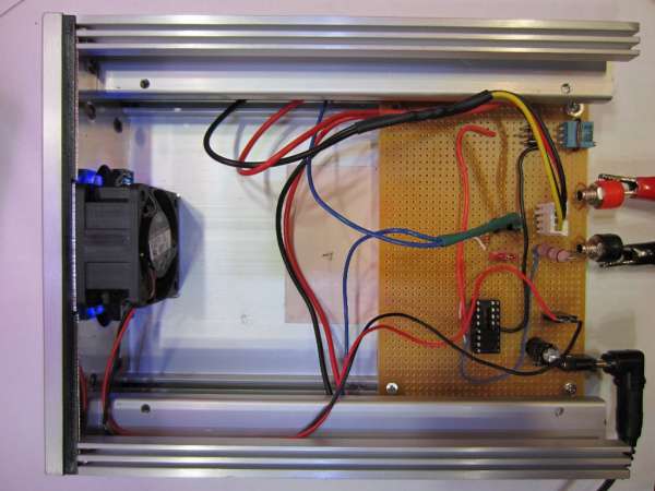
what I ultimately hope to end up with is something like this:

currentload-rev2.jpg


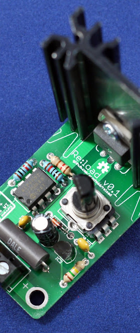
or even better, here's one somebody built that powers itself:

P1010249.JPG

http://www.arachnidlabs.com/blog/2013/02/05/introducing-re-load/

and maybe when I'm done, I can stick them in an enclosure like this:

dummyload1-W600.jpg


none of these devices can draw enough amps to suit my need though.  They have the schematics that tell exactly how it goes together, I just need to figure out how to ramp it up, if I could get it up to, say 10 amps, then I could build 10 or 15 of them and connect them to various connectors on the power supply and dial them all in individually to meet the load requirements for the test I'm working on.

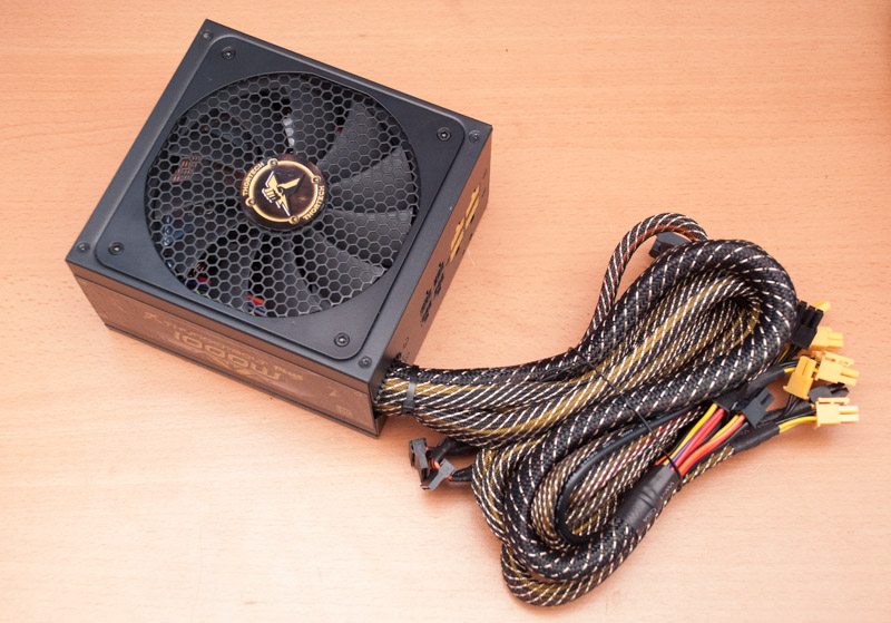
Suppose I'm testing this power supply:

Thortech-Thunderbolt-Plus-1000W-24.jpg


which has these specs:

thortech_thunderbolt_plus_1000w_specs.png


and I'm trying to test the supply at 50% load.
I would need to draw enough amps produce 500W, so without going into research of the proper test configuration put IEEE standards right now, lets just say I'd pull 12A from 3.3V, 12A from 5V and 33.4A from 12V.  If I build 6 constant current load kits that pull 10A each, I could hook 2 to two separate 3.3v connecters at 6A each, 2 to two separate 5v connectors at 5v each, and 4 to four separate 12v connectors at 8.35A each (actually I'd probably use enough on the 12v connector to keep the power draw under 6A so as not to burn wires, but that's a detail I'm overlooking for the example).  and to get this load all I would need to do is plug them in, connect my amp meter, and dial the potentiometer up or down until I read the desired amps.

that is the basic idea, but like I said the problem is scaling up the designs from these schematics.  Since I can't find schematics already dialed up, I have to figure out what parts I need myself.  To figure out what parts I need, I gotta figure out what specs I need, to figure that out, I gotta figure out what the different specs MEAN.

2 weeks ago I didn't even know pots, op amps, or mosfets existed.  I had a general idea of resistors but I'd have to google ohms law to tell you anything useful.  now, I've read up on all this stuff thought I had a reasonable comprehension, so I tore open a power supply to get parts (that's where I got my mosfets) and bought some off-the-shelf op amps from radio shack.

The EE school would (or did?) teach you to use the CHALK-BOARD. You really can NOT talk efficiently about circuits without at least a crayon. Text descriptions are NOT efficient. And while you may not care about your time-efficiency, when asking for help, you need to "make it stupid simple" for the people you are asking.
*******************************************************************
here's the "make it stupid simple" part
*******************************************************************

I didn't go to EE school, hell, I didn't even take college physics.
when I say I'm trying to figure out this op amp, I'm talking basics.

I did a lot of research into op amps, and learned about negative feedback (as in learned of its existance, obviously I haven't figured it out or I wouldn't be here asking for help),

I found videos such as this:
https://www.youtube.com/watch?v=yHhmp_1y42s&list=PL70C5F4CC9B51FE08

even a simulator to let me set up some virtual labs:
http://falstad.com/circuit/

I thought I was getting it so I tried to experiment hands-on.  I'm not good with "crayons" so I copied a bunch of images from google image searches and edited them together in paint to show some of the setups I tried.  I put those in the image I attached to this post

the formula I found says :Vout = Vin(1 + (R2/R1 +R2)) (this is in the image also to be easier to read)

when I'm listing my "attempts" that is physically how I set them up.  I was double and triple checking every connection trying to get predictable results.  These are not the only attempts I made, not even 1/10 of them.  I was at one point using a potentiometer that went up to 100k ohms and combining it with resistors for a voltage divider.  I spent hours on one op amp (two days on the LM741 alone) and then the other trying to figure this stuff out, on the LM724, I only used a single op amp out of the quad.

on the first attempt, I expected to get a Vout of 13.5

Vout = Vin(1 + (R2/R1 +R2))
Vout = 9v(1 + (10 Ohms/10 Ohms +10 Ohms))
Vout = 9v(1 + (10 Ohms/20 Ohms))
Vout = 9v(1 + 0.5)
Vout = 9v(1.5)
Vout = 13.5V

That's not what I got, I've gone through probably 50 different configurations and spent hours testing and experimenting so I can't remember exactly what I got, but the point is that per the math I SHOULD have gotten 13.5

Nevermind the EE degree. Basic Philosophy teaches that you never get out more than you put in, and you usually get less than that. So how would you think "SHOULD see 9.9V" when you only have a 9V supply?

that's where the learning experience comes in, it's supposed to AMPLIFY the voltage, but I wasn't getting it, I spent a lot of time working on attempt 1, 2, and 3, type setups before I realized "oh hey, they don't put the Vs+ and Vs- on a lot of these schematics, I need to research that) So I did.  at first with attempt 4, 5, and 6 type setups I was still not getting over 8 or 9 volts. and by the way:

"...getting values in the 8.?? range."

Be Specific!! Does not hurt to read "8.92V" or "8.53V".

Particularly when it may Matter. In transistor chips, "get less than you put in" often comes in 0.6V lumps. And there's often two transistors between the output and the battery. So if you had reported "8.7V" I/we might say "Ah-ha! Two of 0.6V drops plus a bit of internal resistance.

> my batteries are already not at 100%

Which means WHAT? 9.1V? (A fresh 9V batt reads over 9.0V.) Or 8.1V? Or 3.21V? You MUST keep a sharp eye on battery voltage. Otherwise you spend a day debugging a pedal that works fine with a non-dead battery. As a fledgling power supply tester, testing supply voltage should be obsessive. When bringing-up vacuum tube amps I often have more meters on the supplies than in the circuit.

I pointed out "8.??" because they were similiar results multiple times, but because I was spending so much time drawing power it was starting to weaken the batteries slowly, so one test might be 8.91, later I may get 8.76.  I can't be specific because these tests were multiple, not the same, and I'm not writing this AS I test so I can't work from memory on the specific result.  while I'm sure it matters to some degree, my 3rd attempt is a good example of why I wasn't concerned with the .?? part:

Vout = Vin(1 + (R2/R1 +R2))
Vout = 8-9(1 + (100 Ohms/10 Ohms +100 Ohms))
Vout = 8-9(1 + (100 Ohms/110 Ohms))
Vout = 8-9(1 + (.909))
Vout = 8-9(1.909)
Vout should be between 15.27 and 17.18

regardless of what the .1 and .01 reading on the voltage is, 8.anything is not a correct voltage reading and therefore I'm not concerned with the precision.  I was aware of voltage drop, did keep an eye on my battery, and common sense eliminated that as a problem.

I started thinking about that basic philosophy you mentioned, and not being able to get out more power than you put in.  but I was actually thinking of it in terms of the amplification that I was supposed to be getting was giong to be some sort of "black box" function where it would suppliment the incoming voltage with additional voltage it would get from Vs+ and that's how it would be able to exceed the 9V I was putting in.

after coming to this site and finding that "wire a battery backwards" thing I mentioned in my first post, I did more research and found an explanation that I applied in attempt 7, 8, and 9.  which was a total of 18V, but regardless of the configuration I put everything into, I just could not get any sort of result that came close to what I calculated output should be.

I realize I've been very long winded, and not having an EE background, when asking for help all I know how to do is to follow my own career field as an example.  In IT, if somebody calls me for help, there's no such thing as too much information.  Tell me any facts you can and let me decide what's important and what's not.

things that I've left out here is ALL the experimental setups I've tried. I've only given the most common setups that I was using and a couple of calculations so you could see what I was going for.

some things to keep in mind, I realized I may not be measuring correctly so for each test I measured across multiple points.  Take my 3rd attempt example again.  if I'm expecting to see 15v and I'm getting 8, then I would be aware that I may not be trying to measure the voltage at the correct points, I would test all over the place, and if it was working, then at least SOMEWHERE I should be able to read 15v but I just never did.

in regard to attempt 7, 8, and 9.  It did occur to me that I'm not getting an 18v source, but actually getting a +9vs and a -9vs.  so it seems to me that to have a +18 and -18, I would need 4 batteries in series with the ground going between the middle two.  I haven't hooked this up and tested it though as to me that seems enough power to cause damage to the chip or the batteries or something, and I'd prefer to not have to clean up leaking acid because I didn't take the simple precaution of asking for some advice first, which is where I am now.

I had a headache before I read this passage. It's worse now. Maybe I'm overlooking an obvious? But it isn't clear WHAT you have done.

hopefully I've cleared up motives, what I've tried so far, and what I'm trying to do.  I realize I'm hard to follow and long winded, but this is an important project that I need to accomplish.  If I had a more knowledgable friend to do it for me, or the money to purchase equipment instead of build it myself, I'd be right on it, but unfortunately this is the boat I'm in.  Any assistance would be very helpful, but if I don't get it then I still gotta get it done, it's just going to take longer and be harder, giving up isn't an option.
 

Attachments

  • experiments.jpg
    experiments.jpg
    186.7 KB
> long winded

TL;DR.

2,911 words? I think you got me beat, at least for forum posting. The longest piece I have here is 9,000 words and that took a week; you did a third in 5 hours. Ah... you are a Writer. At 2 cents a word (the rate since Twain complained) that's a very nice lunch.

You are over-stating the resistor problem. The "12V" output is either very-close to 12.0V or it has failed. If it is 12V, a 1 Ohm resistor sucks 12 Amps, a 10 Ohm resistor sucks 1.2 Amps, or a 12 Ohm resistor sucks 1 Amp. These will be BIG resistors. Nail a bunch them to a board with binding-posts and jumper-straps. A 120 Ohm resistor draws 0.1 Amps and tests the light-load end of the range. One 10 Ohm resistor is 1.2A, typical for the PCs I use. Six 1 Ohm resistors sucks 72 Amps, which is a near-match for that 83A supply. Each 12V resistor may simply be labeled with the Amperes it pulls at 12V. So you just start with one small resistor, then strap-in more and more until the 12V goes down.

Or until the heat sets your board on fire or drives you from the room. 1,000 Watts is a respectable room-heater. FWIW, any reasonable dummy-load, any technology, will throw the same heat. (If this rig ran 24/7 it *might* be justified to reconvert that test-power back to electricity to sell back to the utility company.... but not for one KWH a few times a month.)

At some point short of shutdown you can read your wall-input currents etcs.

> the image I attached to this post

Ah. You missed the Aug 1967 issue of Pop Electronics "Basic OpAmps". You are like kids today who don't know a horse has 4 legs and a seat and a mouth and another end. Try to hang on the tail, get their fingers nipped, step in poop.... And Wikipedia is NOT telling you some basics.

Try http://www.ti.com/lit/an/slod006b/slod006b.pdf (2Meg PDF). It covers good ground. I do see spots where Ron knows his chit SO well that he skimps important concepts.

Breadboard the plan below.

Use over-10K resistors with opamps!! One of your plans shows 9V across a 10 Ohm resistor which is nearly One Ampere. A significant fraction of the current in your wall outlets. Neither small chips nor 9V batteries can pull that kind of load. 10K loads, they are OK with.

(Yes, at the far end of this affair you seem to have an 83 Ampere source. However you will use op-amps to compute a 1/10,000-th scale representation of the current you want, and use a monster MOSFET(s) to suck the supply.)

Concept: many wires in a practical system, many overlapping circuit loops. "Usually" we common one side of most loops and call it Common, or Zero Volts. (Also called "ground/earth" but battery systems generally don't tie to dirt, a dirt-rod is "often" optional for basic functionality though *essential* for safety when Stuff Goes Wrong.)

You used the Inverting connection. This is useful in real systems and also for beginners.

Implication: you did not use +/- math (that I see). But a positive input, inverted, is a negative output. So the op-amp must output *both* positive and negative. If you only had, say, the +12V output on a PC supply, you could not (directly) output negative voltages. That is in fact why PCs have a legacy NEGative 12V supply. With both + and - supplies you can output + or - voltages.

PC supplies are balky dangerous bench supplies for basic learning, use two 9V batteries... I done months of experimentation that way.

In the plan below, with 10K input and 10K feedback, a +1.54V input causes a -1.54V output. If you don't get that, you have a bad/wrong connection. With 10K in and 22K feedback we compute a gain of (-)2.2, so +1.54V in makes -3.39V output. 47K, -7.24V (probably). BUT 68K computes to -10.5V. You only have -9V supply. This is impossible. You will get something shy of 9V, maybe shy of 8V.
 

Attachments

  • manaduar1.gif
    manaduar1.gif
    17.2 KB
ok, some useful advise starting to come in.

You are over-stating the resistor problem. The "12V" output is either very-close to 12.0V or it has failed. If it is 12V, a 1 Ohm resistor sucks 12 Amps, a 10 Ohm resistor sucks 1.2 Amps, or a 12 Ohm resistor sucks 1 Amp. These will be BIG resistors. Nail a bunch them to a board with binding-posts and jumper-straps. A 120 Ohm resistor draws 0.1 Amps and tests the light-load end of the range. One 10 Ohm resistor is 1.2A, typical for the PCs I use. Six 1 Ohm resistors sucks 72 Amps, which is a near-match for that 83A supply. Each 12V resistor may simply be labeled with the Amperes it pulls at 12V. So you just start with one small resistor, then strap-in more and more until the 12V goes down.

12v on 1 Ohm to get 12 amps is 144 watts, most resistors I've seen can handle portions of watts.  and I'd have to sustain that load at least 15 minutes.  what's more is the time involved.  lets say I start out at 8am reviewing a 600W power supply, first I need the 10% load test, so I figure out how many of which resistors I need then nail them to a board and do the load test.  next is 20%, gotta re-calculate resistors and make a new board.  then 50%, then 80%, then 100%, now I check thermals, take photos, audio measurements.....(not all in that order but stuff that has to be done throughout the testing).  and then I move on to a 750W review.

I'd be spending half my time sorting out the resistors, which would be a problem of itself but if it were the only option I had lets say I'd go with it.  at 144W I'd burn out any resistor I could find, or I divide the load across enough resistors to handle it, like 144+ just for the 10% load test alone.  Or maybe there's a brand of resistors out there that can handle 144W continuous or something close enough to it that I'd only need a small number of them, would their resistance be constant?  Doesn't the efficiency of a resistor change based on heat?  if I get all set up, I'm pulling 10% and wait the requisite 15 minutes, will it still be the same or will heat have caused the resistors to change a little?  if so I can't dial in, I have to rebuild and start over.

I'll admit I haven't looked too deeply into the option of just using resistor banks because of these issues, so there's a chance it may not be as bad as I'm making it out, but between time, cost, and effort, it just doesn't appear viable to meet standards.

Ah. You missed the Aug 1967 issue of Pop Electronics "Basic OpAmps". You are like kids today who don't know a horse has 4 legs and a seat and a mouth and another end. Try to hang on the tail, get their fingers nipped, step in poop.... And Wikipedia is NOT telling you some basics.

??? Um,.....yeah, missed that one, lol.  I think the jist of what you're saying is that I don't know the first thing about op amps and I've been googling them to learn and there's holes in my education.  In which case, yes, I agree, I put in a lot of effort to learn, but obviously if I had gotten everything I needed I wouldn't need to ask for help.  That's why I'm here, I would/could provide a laundry list of my sources for research, but I'm not trying to brag on how hard I worked, I'm just trying to get done.

Use over-10K resistors with opamps!! One of your plans shows 9V across a 10 Ohm resistor which is nearly One Ampere. A significant fraction of the current in your wall outlets. Neither small chips nor 9V batteries can pull that kind of load. 10K loads, they are OK with.

noted, and I had tried higher value resistors, anywhere from 10 Ohm up to 1m.  I just didn't put them in the pictures because I was trying to only give an example of the general setups I tried.  If I listed everything I've already tried, it'd make my last post look like a slip from a fortune cookie. :/

(Yes, at the far end of this affair you seem to have an 83 Ampere source. However you will use op-amps to compute a 1/10,000-th scale representation of the current you want, and use a monster MOSFET(s) to suck the supply.)

agreed, I realize that from the many current load examples and "how-to's" I've found.  And I'm not trying to use the op-amp to suck the amps, I was just trying to experiment with the op-amps and see a result that I could actually predict with calculation.

I did my research and thought I had an understanding of everything so I wanted to put it all to the test and see if it worked like I thought.  I was taking it one component at a time, and in order to cut down on the confusion I was just going with numbers that would be simple to do the math. 

the basic formula: "Vout = Vin(1 + (R2/R1 +R2))"

I call that the basic formula because, per my research and if I understood everything correctly, I have 3 variables to control and manipulate.  if I apply 9v, and use a 100k resistor for R1 and a 200k resistor for R2, I just plug those values into the formula and see what voltage I'll get out.  how about 1.5V with a 10k and 100 Ohm, etc, etc....

that's all I've been trying to do so far, but I've had no luck, not once have I been able to calculate a result or get a result that I calculated.

Concept: many wires in a practical system, many overlapping circuit loops. "Usually" we common one side of most loops and call it Common, or Zero Volts. (Also called "ground/earth" but battery systems generally don't tie to dirt, a dirt-rod is "often" optional for basic functionality though *essential* for safety when Stuff Goes Wrong.)

understood, I didn't run a line outside and drive a lightening rod in the earth to use as ground.  But I see this as one of the points where I could be making my mistake, which you drew in your picture a different setup that I want to ask about.

PC supplies are balky dangerous bench supplies for basic learning, use two 9V batteries... I done months of experimentation that way.

agreed again, I'm only using batteries, and the only reason I'm using 9V batteries instead of, I dunno AA batteries maybe, is just cause they would be easier to work with.  those posts give me something to "grab onto"  so that I can hook up wires easier.  Just thinking of the tools I have available.  I'm using alligator clips to connect to my battery.  with AA or some other sort of battery I couldn't think of a firm way to fasten the wires.  I don't have anything like the box in a remote where I could put the batteries and have posts to wire to, so what, hold them on with a rubber band?  I dunno, said it a dozen times already but this isn't my thing so I'm trying to eliminate some headache and details so I can focus on just understanding the basic functionality.

You used the Inverting connection. This is useful in real systems and also for beginners.

Implication: you did not use +/- math (that I see). But a positive input, inverted, is a negative output. So the op-amp must output *both* positive and negative. If you only had, say, the +12V output on a PC supply, you could not (directly) output negative voltages. That is in fact why PCs have a legacy NEGative 12V supply. With both + and - supplies you can output + or - voltages.

This is the second statement I could use more detail and clarification on, I agree this is somewhere I could be making my mistake.

In the plan below, with 10K input and 10K feedback, a +1.54V input causes a -1.54V output. If you don't get that, you have a bad/wrong connection. With 10K in and 22K feedback we compute a gain of (-)2.2, so +1.54V in makes -3.39V output. 47K, -7.24V (probably). BUT 68K computes to -10.5V. You only have -9V supply. This is impossible. You will get something shy of 9V, maybe shy of 8V.

So I don't understand how you got these results, but maybe you could explain a couple of things first?

you said I used the inverting connection, I applied the positive charge to the non-inverting input on the mosfet though.  At least my understand of my example that's how I'd state it.  Everything I've seen on negative feedback has put the voltage divider of the inverting input, and the end going to ground.  So I hook up my positive post of my battery to the non-inverting and I take ground to be the negative post of the battery.  I've tried using ground between my other two batteries (the ones on the right in the pics we been using) but then I had nothing hooked to the negative of my input voltage so the loop wasn't closed.

you've flipped the input battery and hooked it up backwards of how I had it AND connected the positive post to both the non-inverting input AND the ground connection of the supply batteries, can you explain why you did these, what's this do that my connection didn't do?

your math results are giving me something to think about also, per my math, If I used 2 10k resistors and a 1.54V input:

Vout = Vin(1 + (R2/R1 +R2))
Vout = 1.54(1 + (10k/10k +10k))
Vout = 1.54(1 + (10k/20k))
Vout = 1.54(1 + (.5))
Vout = 1.54(1.5)
Vout = 2.31V

so my math says I should get 2.31v, but you're getting -1.54.  Now what I hadn't thought of or looked at while I was working was voltage DIFFERENCE.  you're inputting +1.54, getting -1.54, so a total difference of 3.08v.  So this is something I should start taking into consideration, but my initial thought is that this raises more questions than it answers.  your calculations only invert the voltage without amplifying it, so even though it's negative our math doesn't match, and even if I look at the voltage difference it doesn't match either.  Can you help me understand your math and how/why you get those numbers?  or what's wrong with the math I'm doing?  Am I using the wrong formula, cause I've seen it on multiple independent sources as the way of calculating output?  does this have to do with the changes you made in connecting the input battery?

We're starting to get into something I can learn from here, I really appreciate the help a load.
 
It so happens that I'm in the process of building/buying a constant current load to test a 1.5kWh battery pack + BMS we've developed.

To start off: http://www.ebay.com/sch/Business-Industrial-/12576/i.html?_from=R40&_nkw=electronic+load

For me, I've found that this design might not meet the McDonald's test. This test, which I apply to tasks which don't have much fun, learning opportunities or unique customizations, goes something like this:

If I were to subtract the cost of raw materials I'd need to build the system from what I would have to pay to buy an equivalent device, and divide it by the expected number of hours I'll sink into this, would it be smarter economically to flip burgers instead?

It may not hurt to scout the 'bay, particularly if you live in the US.

Having said that:

manaduar said:
[...]lets say I start out at 8am reviewing a 600W power supply, first I need the 10% load test, so I figure out how many of which resistors I need then nail them to a board and do the load test.  next is 20%, gotta re-calculate resistors and make a new board.  then 50%, then 80%, then 100%, now I check thermals, take photos, audio measurements.....(not all in that order but stuff that has to be done throughout the testing).  and then I move on to a 750W review.[...]

So pre-build a number of likely configurations. Better yet: make yourself a load kit which you can vary by placing sections in parallel. If you want to go for fancy: http://en.wikipedia.org/wiki/Resistor#Resistance_decade_boxes

manaduar said:
[...] Or maybe there's a brand of resistors out there that can handle 144W continuous or something close enough to it that I'd only need a small number of them,[...]

Just a few examples:

http://www.ebay.com/itm/4-Ohm-4R-100W-Watt-Power-Metal-Shell-Case-Wirewound-Resistor-/250911322824
http://www.digikey.com/product-detail/en/FVT10006E1R000JE/FVT100-1.0-ND/257602

manaduar said:
[...]would their resistance be constant?  Doesn't the efficiency of a resistor change based on heat?  if I get all set up, I'm pulling 10% and wait the requisite 15 minutes, will it still be the same or will heat have caused the resistors to change a little?  if so I can't dial in, I have to rebuild and start over.

All resistors are 100% efficient at turning electrical energy into thermal energy.

Resistance does change with temperature. There are a few other factors, including time, but temperature is dominant for pretty much all devices which are sold as resistors. This is the temperature coefficient listed in the datasheet. If a resistor's temperature coefficient is too great for your purposes, you can cool it (by pointing a fan at it or by bolting it to a big chunk of metal), you can pick a resistor with a better TC (and pay more), or you can go for a bigger resistor which in itself may be better at getting rid of its heat.

Big resistors tend to be wirewound; wirewound resistors resemble coils, coils have inductance. For my purposes that doesn't matter (the terminal voltage of a big battery is - for all intents and purposes - DC); a PC supply may or may not show funky interactions when presented with a considerable amount of inductance. Something like http://www.digikey.com/product-detail/en/PF2272-1RJ1/696-1362-ND/4058826 does not have this problem (but is more expensive).

I am somewhat concerned that you do not mention anything about desired accuracy, or dynamic behavior (other than "ripple is of particular concern for overclockers"). PRR asked something similar. It's very hard to specify let alone build a measurement setup if you don't know just what you're trying to measure.

(On a related note, a reputable reviewer will document their setup in sufficient detail that others can reproduce the measurements. This may be easier when you can say "Transistor Devices DAL 50-15-100 DC Electronic Load" (bonus points for calibration data) versus "I used this bunch of resistors I found on eBay.)

JD "can't get what you want 'till you know what you want" B.
 
> first thing about op amps and I've been googling them to learn and there's holes in my education.

There's BIG holes in what is available on the webs. Stuff "well known" before 1996 tends to be overlooked. There are corners where some branch of ancient knowledge is wrote-up, but they tend to be incomplete.

> I applied the positive charge to the non-inverting input on the mosfet though.

I hope that is a mis-typing not a mis-understanding.

> you've flipped the input battery and hooked it up backwards of how I had it AND connected the positive post to both the non-inverting input AND the ground connection of the supply batteries,

I don't think so. Maybe someone will spot my error.

> I couldn't think of a firm way to fasten the wires.

Don't scrimp connections. Radio Shack probably still has AA-batt holders. Beats heck out of rubber bands; and safer than soldering to a battery.

> most resistors I've seen can handle portions of watts

Are there electric trains in your area? Unless fairly new, there's a 50,000 Watt resistor on the roof. (Bad idea to steal it-- 600 Volts and probably a couple tons.)

2,000 Watt resistors retail:
http://www.digikey.com/product-detail/en/1879456-1/A105579-ND/2367799
http://www.digikey.com/product-detail/en/1-1879456-3/A105663-ND/2367811

They come in all sizes and many values; I just sorted for Watts-up.

> I start out at 8am reviewing a 600W power supply

Resistors at known voltage can be marked in POWER. In the 12V bank, 14.4 Ohms sucks 10 Watts power at 12.0V. (This can be 15 Ohms and 360 Ohms permanently paralleled.) So you have switches to throw-in 10 Watts at a time. Maybe a 5W and a 100W to save time. Just add the Watts numbers. Similar for 5V and 3V. (I suppose you know the -12V is very nominal.)

Just to be different you can use car lamps. 1157 tail lamp has a 1 Amp filament, 12 Watts. Headlamps are around 40 Watts. Wire a bunch of sockets and switches. "This power supply can throw light a quarter mile into the woods!" Uh, this does raise a problem: lamp turn-on current is much higher than running current, so you'd have to turn-on one at a time. Since you might be doing that to plot performance versus 10%-20%-50% load, that might be OK.
 
Consider heat.

You seem to want up to 500 Watts load.

You can get a 500 Watt work-light cheap at the Home Store. Put it in that box you propose... oh, won't fit. So disassemble it and transplant the socket and lamp. If you don't shock or burn yourself, you will find it runs VERY HOT. Probably hot enough to distress Silicon.

You also want the PS and load all tied together so you don't have HIGH-power loose wires at every fumble. I'm thinking a BIG desktop case. It has the PC mount, and space for load. Enough space? I'd want more. OTOH you have to keep these wires short because there is big voltage drop at 83 Amps (even 41 Amps). The "100 Amp" wires to my house have conductor 1/4" diameter. And I have voltage-drop trouble. True, my wire is longer. OTOH the drop is bad relative to 120V. At 12V the drop is relatively 10 times worse. So your wiring is also a mechanical (big chunks of copper) problem.

What is a big CPU these days, 130 Watts? So 500W is like four of these. I have not seen a quad-socket mobo in a long time. (Essentially, since they multi-cored so bad the Watts went way-way up.)

Your MOSFETs will need heatsinks. Lots of classic approaches. But modern CPU sinking make the old ways look old. And expensive compared to commodity PC parts. I'd get BIG CPU heatsinks and drill/mount 1 or 2 MOSFETs each. That should throw >100 Watts and still be a survivable temperature. 4 such sinks should do it.

You need to get the hot air out of the case. I'm thinking kitchen fan, but several of the largest PC-case fans might do.
 
Having mercy.

The plan below is THE basic tool to do what you want. Self-powered 0 to 10 Amp current sink. Turn the pot to dial your current. (If you find a sweet 0V-5V USB DAC you can control it from your laptop.)

It can be extended with more MOSFETs and resistors but you need an op-amp for each MOSFET (the LM324 has four; it also handles the zero-volt input which some opamps won't like; it's also really cheap.)

This is for the 12V lines. Problem at 5V 3V is that it can take over 5V just to bring the MOSFET up to high current. I'm out-of-touch on what MOSFETs are available today (they go out of production too fast) and what voltage and current they do. Here I have assumed the "+12V" is really 12V very-near, the LM324 can slew up above 10V so the MOSFET gate-source is 5V (or less as needed), and budgeted 5V on the resistor, for accuracy and to help share the monster heat load. (Power resistors can run hotter than Silicon so can take less space per Watt.)

The resistor is also a safety-stopper. When the MOSFET fails dead-short, the current can't go to infinity, only to 12V/0.5r= 24 Amps. Yes, the resistor will probably burn-up but classic wire resistors are pretty reliable about failing open, not short.

The opamp compares the set-voltage from the potentiometer with the voltage across the big resistor. Ohms Law forces this to a current.
 

Attachments

  • manaduar2.gif
    manaduar2.gif
    4.6 KB
Back
Top