[BUILD] CAPI LC53A~500 Series~Love Child EQ Kit~Official Support Thread

GroupDIY Audio Forum

Help Support GroupDIY Audio Forum:

This site may earn a commission from merchant affiliate links, including eBay, Amazon, and others.
ok, so one of my units has a weird anomaly in the 7K Shelving band.  basically, if i switch it to Hi Shelf mode, and set the switch to 7k, any gain setting results in gain throughout the entire frequency range.    Switching from 7K to another frequency results in a low freq "thump" into my interface.  That same thump occurs if I toggle from Hi Shelf to Hi Peak, while on the 7K band.  this doesn't happen for ANY OTHER frequency band.  i tested everything else.  Jeff said that the specific components to check at C23, C25, R13 and the Hi Freq Switch.  I've desoldered and resoldered those parts a couple times and the issue remains.    Any ideas?  How could i test if the capacitors are good and not borked?  again it's **only** the 7K Shelf where this happens. 
 
Chuck, I just sent a reply to you on Facebook. I think we need to narrow down our ways of communication cuz I can't keep up with all of them. If you are having trouble with something, lets just use the build threads and not private messaging on Facebook. That way, others who may experience the same issues can benefit.

So, to reiterate my last private message, if it is not F4 (which is the ground for the hi shelving band) it is most likely C23 which is in parallel with C25 which then has R13 in series to F4. Since the "pop" only occurs when the GH is switched to or from the 7k position, this tells me it has nothing to do with the peak/shelving switch or the inter-board pins/headers. It could also be the GH switch. Check for continuity when the switch is at the 7k position, between the B pin and pin 4 of the attached pic.
 

Attachments

  • ScreenShot017.png
    ScreenShot017.png
    119.8 KB
ok, the continuity tests were sucessful:

from pin B to pin 4 has continuity.
from pin B to both pins on C25 had continuity
from Pin B to both Pins on C23 had Continuity
from Pin B to both pins on R13 had continuity, as well as resistance around 1.82K which should be 2.49K.  Would that cause the problem?


edit:  resoldered R13, now it's showing up as 2.49K

Also, the pop occurs when switching TO/FROM Peak/Shelf when the GH switch is on 7K. 

basically, switching to/from 7K Hi Shelf results in a LF "boomp". 

edit2:
I discovered another source of the "boomp".  this happens on all 4 modules.  regardless of band/gain selected, the HPF switch gives a bump around 5hz, which comes in around -36dbFS on my interface. 
 
mulletchuck said:
....I discovered another source of the "boomp".  this happens on all 4 modules.  regardless of band/gain selected, the HPF switch gives a bump around 5hz, which comes in around -36dbFS on my interface.
This is normal and expected as the switch is interrupting the audio signal by bypassing the series C's used for the HPF.

I think at this point, I would try removing those 2 caps, but only one at a time. Desolder C23 from the PCB and see if the issue is resolved. Keep in mind, the knee of the 7k freq will be changed but we are only trying to see if there is an issue with one of the caps. Then, reinstall C23 and remove C25. Check again.
 
Removed C25.  No change.  Reinstalled C25.
removed C23.  ISSUE IS GONE!!!  woot woot!

So i need to replace C23.  awesome!!  Add that to the list of things that need fixing/replacing :-D  Convert gain pot on VP312 to GainSwitch, convert F76 Input/Output pots to Switches with VP GainSwitch kits, replace blown C10 on VP312DI, inspect slot #2 on Rack#2, cuz the big caps in the VP26 and VP312 have blown as a result of being in that slot. 
 
mulletchuck said:
...removed C23.  ISSUE IS GONE!!!  woot woot!
Well, I can send you a replacement C now or when you order the other bits you need. Just don't let me forget. Once past the switch, I knew it should be easy to find. Glad it is sorted.  8)
 
Got mine on Jan 2nd. I had to pay 179€ to customs here in Germany for the 2 kits.

Started to build and must say these are a real pleasure to build! Everything fits fine, everything is there and all the parts are top quality. I have to confess that I spoiled a couple of the small Millmax sockets right away. I consider myself a decent solderer, but was a little too careless in the first place . The extra 3 sockets in the kit really saved me!

Since I'm not only building because it's fun and to have a nice new toy, but also to learn about circuit design I would very much appreciate a schematic.
 
mulletchuck said:
i'm pretty sure the only way you'll get a schematic is if you rev-eng it from the traces on the PCB  :-\

Hm, not so much fun with a multi layer pcb. It's too late now anyways. I have finished my pair. And they sound just magnificent!

http://db.tt/WdGFe2gf
 
Thanks, Udo!
Yours aint's so bad either. How do your Love Children compare to the EQP-1s? How do you decide to use the one or the other?
 
901 said:
Thanks, Udo!
Yours aint's so bad either. How do your Love Children compare to the EQP-1s? How do you decide to use the one or the other?
Hi,thanks for the kind words.
Personally they are both absolutely great and very musical eqs,but they aren´t directly comparable.Both have their points where they work best.I´d say I use the lovechildren more on single channels and instruments incl. vocals while the pultec is more in use for complex signals like a mix or so because of its´"bump".But that´s just an example,I´m sure both do fantastic jobs on a lot of things.
Conclusio:Best to have them both-and lots of them ;D

Cheers,

Udo.
 
Hi

Just cut a pad when trimming the leads tight on the LC-EP board.  I need to work out how to join this back in the circuit?  Any chance of getting a schematic. 

Capacitor is C43 Pad next to F4, if schematic is not available.


Electrobumps said:
....Capacitor is C43 Pad next to F4, if schematic is not available.
That pad is a connection to the ground plane. If you have solder inside the thru hole, you should be OK as the ground plane is on the top side of the PCB. I would measure for continuity between that pin and the pin of C44 or C45 that is closest to the edge of the PCB. Those are also connected to the ground plane.
 
jsteiger said:
That pad is a connection to the ground plane. If you have solder inside the thru hole, you should be OK as the ground plane is on the top side of the PCB. I would measure for continuity between that pin and the pin of C44 or C45 that is closest to the edge of the PCB. Those are also connected to the ground plane.

Thanks for getting back to me so quickly on that one.  It would seem that I got away with removing the pad and it is getting to ground.

Just finished the two units.  I have one glitch on one unit. When the HF shelving is selected.  One unit gives a lot of low end boost when 7K is the selected freq other freq's are fine, does not happen when notch/bell is selected and Eq seems to function normally. 

I have swapped the EP board with the unit that was working and the fault has moved with the EP board. 

I have made visual checks of all components on both boards and they seem to mirror each other.  For good measure I also re-flowed switches 4 and 5.

Any ideas on where to start tracking this down? 
 
Scroll up towards the top of this page and you will see some correspondence between myself and mulletchuck. He had a similar problem, oddly with the same exact setting. I would follow the steps I told him to try. Turned out to be a faulty cap. Keep me posted.
 
jsteiger said:
Scroll up towards the top of this page and you will see some correspondence between myself and mulletchuck. He had a similar problem, oddly with the same exact setting. I would follow the steps I told him to try. Turned out to be a faulty cap. Keep me posted.

I searched this post late last night and the answer was right under my nose!!!

Anyhow, I've removed C23,  The cap is shorting against itself in and out of the circuit.  When removed I have no HF band, but I guess this is to be expected.

Lucky I managed to put the faulty cap in C23 like mulletchuck for quick diagnostics. The other 3 6800J caps across both units do not short. 


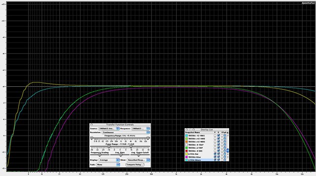
LC53A and TB550A response, EQ flat and filters in.

Click this link for a full size pic

8444163080_78b161614b_z.jpg


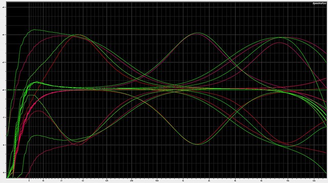
LC53A (green) and TB550A (red) 6dB boost and cut response,  50, 1K5, 15K.  You can see the effects of the differing amp response on the curves.  The TB550A boosts also drop off of marked boost as frequency increases. 

Click this link for a full size pic

8444163314_6358fcf025_z.jpg


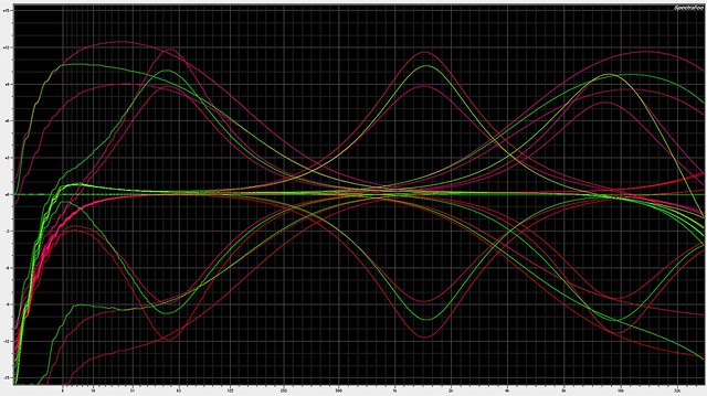
LC53A 10dB (green) and TB550A 9dB/12dB (red) boost and cut response,  50, 1K5, 15K.  The apples versus oranges part of the show, gain steps that don't coincide.

Click this link for a full size pic

8444163256_0f1b1703f9_z.jpg


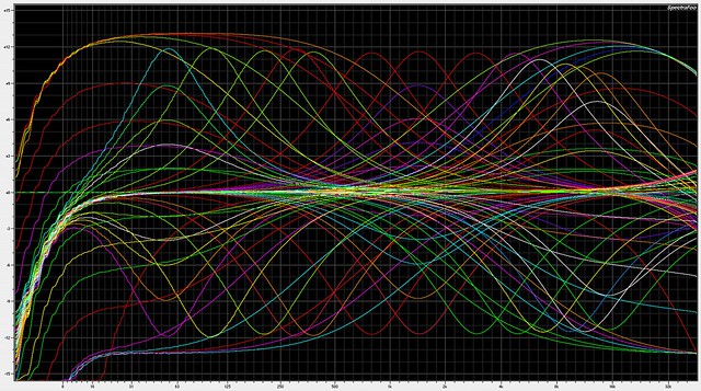
TB550A curves for a broader overview of this general EQ type.  This is all the +12 and -12 settings, both peaking and shelf, and 50, 1K5, and 15K have every gain step shown. 

Click this link for a full size pic

8444162906_f269812606_z.jpg


Latest posts

Back
Top