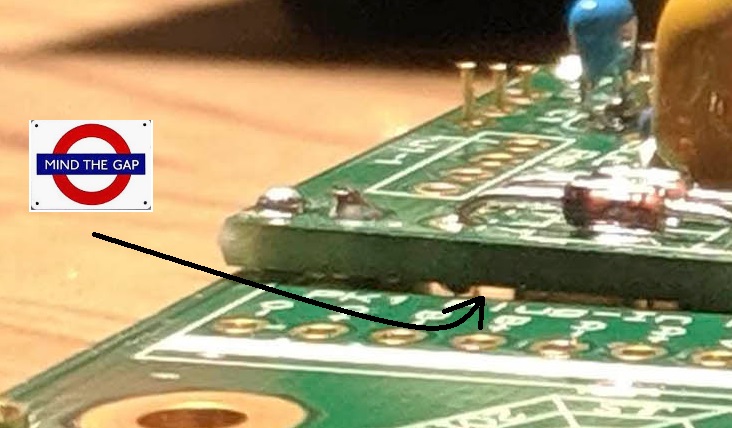
I have a completed VP312DI-5 however when I power it up for initial testing, I noticed a few issues.
1. 600z T-Pad Attenuator does not control the output, i.e., unit stays at the level the input gain switch selects where Full CCW is 0 gain right? When I step CW signal gets louder as expected, but the output attenuator has no effect.
2. A1 test good in my DOA/Op Amp test rig.
3. If I set my signal generator (NTi MR Pro outputs a consistent balanced signal level due to its feedback circuit design) to 0dBu at 400Hz, as expected the 312 output voltage indicates when the Gain is stepped. The MR Pro displays the actual input impedance seen when looking into the 312 input circuit. Appears OK. MR Pro also displays the relationship between the Input XLR Pin 2 and Pin 3. If the 312 Input is fed a balanced signal, and all is OK, the graphic indicates signal halfway between Pin 2 and Pin 3. It can also move hard to P2 or P3, indicating if unbalanced and polarity. I'm telling you this as the 312 appears to be OK input-wise.
4. I have measured the 312 output levels at +24dBu up. Knowing the input signal level (0dBu), when activating the -20 PAD, the output drops somewhat as expected.
5. I have gone over both Xformers, PBs and the two relay circuits (RLY1 and RLY2). All appeared OK.
6. I would venture to guess that a high percentage of 312DI build issues, stem from the relay circuits. Those two relays determine the signal flowing or not flowing. Relays being located on daughter PCBs, potential failure-points would run with PCB-PCB header pins and if solder joints are solid. I did go over both relay circuits. Seems OK.
That is about as far as I have gotten. Ideas and suggestions needed.
Thanks


