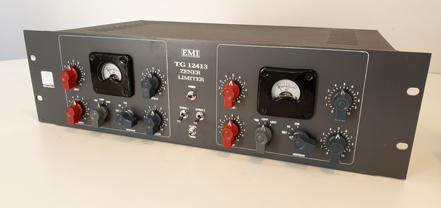
[BUILD] fripholm's TG1 Zener Limiter boards - support thread

GroupDIY Audio Forum

Help Support GroupDIY Audio Forum:

This site may earn a commission from merchant affiliate links, including eBay, Amazon, and others.
thanks for the reply, but i still don't understand it too well.
r8 will always be 82k?
Can I leave the trimmer instead of changing it for the resistor?
Sure, no problem.

The way this bit of fine tuning works is that the trimmer is used to determine an optimal resistance value, and then R7 and R8 can be used in parallel to get as close as possible to that value with fixed resistors. This means that the values are not necessarily going to be the same as the example in the build guide — that is just a sample of how it could work out. Your value will likely be different, and you can use a simple parallel resistor calculator online to work that out (or do the math yourself, the equation is pretty simple).

Alternatively, and easier, I think you can just leave the trimmer in there with no issue.
 
Last edited:
Short answer: Only the trimmer is needed, omit R7 and R8.

TLDR; On current board versions, you would use either a trimmer or R7 and R8 in parallel (for consistency with older revisions) in this location. Earlier versions had no trimmer footprint at all but you had to 'hack' one in there temporarily to determine the correct value. After that you would replace it with two resistors in parallel that have (together) the resistance of the trimmer.

Juanaca, there's math behind parallel resistors (look it up) and there's a link in the guide to a simple parallel resistance calculator. You would use the calculated values for R7 and R8. It didn't have to be 82k all the time :sneaky:
 
Last edited:
Many thanks to both of you for the explanations, I think I am already finding out, what I still cannot understand is because there is a trimpot of 10k and not higher when higher values such as 82k are being shuffled.
sorry for being so persistent.
 
Many thanks to both of you for the explanations, I think I am already finding out, what I still cannot understand is because there is a trimpot of 10k and not higher when higher values such as 82k are being shuffled.
sorry for being so persistent.
Just use the trimmer to make it simple.

For the purpose of edification, if you are interested: when two resistors are in series (one after the other), the total resistance is calculated by simply adding their values together. When two resistors are in parallel (side by side), the total resistance across them is calculated as 1/Rtotal = 1/R1 + 1/R2.

To show an example of each, let’s use the sample values from the build guide for R7 and R8 (3.9k and 82k).

If these were in series, the math would look like this:

3,900 + 82,000 = 85,900 ohms

If these resistors are situated in parallel, however (as they are in this circuit), the math looks like this:

1/3900 + 1/82000 = 1/Rtotal

When you solve for “Rtotal” in this equation, you end up with 3,722.9 ohms. This is why a 10k trimmer can be interchanged with this pair of resistors.

As you can see, the same two resistor values can yield very different total impedance depending on how they are arranged.
 
Last edited:
Just thought I'd show my finished build :)
Thanks fripholm for the project, the guide was very comprehensive.
I ended up making my own knobs and silkscreening a frontpanel, 3D printed Sifam style coverings for the cheap eBay VU meters.
Putting the power supply in a remote box cured my hum woes, as well as keeping the audio transformers away from each other.
20190906-084339.jpg


Hit me up if you're interested in knobs for this project :)
Hi baddy
Do you still have the knobs for sale ?
 
Oh thanks for replying 👍 how can I order those ?

No offense, but is there something not clear about contacting/ordering from me in the very first post of this thread? I'd really like to optimize if it is. Thanks!
 
No offense, but is there something not clear about contacting/ordering from me in the very first post of this thread? I'd really like to optimize if it is. Thanks!
Ops sorry buddy it’s my very first time buying here so didn’t read everything my mistake, everything is very clear 👍
 
Hey guys, I am gathering parts for this build and I have a question about the transformers. Apart from ratios are there specific impedances I should be looking for? Do you guys have suggestions of the originals or what works best in this build? Thanks in advance. Cheers.
 
Hey guys, I am gathering parts for this build and I have a question about the transformers. Apart from ratios are there specific impedances I should be looking for? Do you guys have suggestions of the originals or what works best in this build? Thanks in advance. Cheers.

10K:10K for input and 600:600 for output. Ideally with taps so you can step them up or down. I think transformers have been discussed extensively on this thread so you should find all the info you need.
 
10K:10K for input and 600:600 for output. Ideally with taps so you can step them up or down. I think transformers have been discussed extensively on this thread so you should find all the info you need.
Great thank you so much. I haven’t gone through the whole thread yet…I am getting a little impatient I guess haha.
 
Try 1+1:1+1 for both in and out transformers so you could experiment and see (hear?) what sounds best to you. :)
 
Hey guys, I am gathering parts for this build and I have a question about the transformers. Apart from ratios are there specific impedances I should be looking for? Do you guys have suggestions of the originals or what works best in this build? Thanks in advance. Cheers.
I used Sowter trannies for my build. Sounds amazing! 1460 & 1461
 

Attachments

  • D5873042-C099-472B-901D-7761676213F7.jpeg
    D5873042-C099-472B-901D-7761676213F7.jpeg
    198.6 KB
Sorry for the question, where is the cold signal connected to the output of the input transformer? Thank you
 

Attachments

  • 62CC8995-FC84-4062-9100-DFD36815125E.jpeg
    62CC8995-FC84-4062-9100-DFD36815125E.jpeg
    138.1 KB
This is the symbol for ground (GND) in the guide.

More recent versions of the board (from 2.5a I think) should have a solder pad for GND next to the BYP1 connector. If yours is older - which I doubt - just wire it to the nearest GND pad from this location. R2 has one, so has R93 - it's the round pad with a little cross through it.

My units have the input and output transformers on a separate board and they share the GND connection from the output. Either way you'll be fine.
 
@fripholm
I've got a quick question regarding transistors: is there a reason you are using specifically BC550 and BC559 in the BOM or would 549 and 560 work just as well? Also is the high hfe of the C classification really necessary?
 

Latest posts

Back
Top