[BUILD] GIX-51X tube preamp

GroupDIY Audio Forum

Help Support GroupDIY Audio Forum:

This site may earn a commission from merchant affiliate links, including eBay, Amazon, and others.
mulletchuck said:
Can you elaborate on how C11 was too big?  pin spacing?  too large a diameter?  too tall? 

Diameter.  Just a little tight in that area of the pcb to fit that one in there.  You're replacement should fit fine.
 
Hey Guys,

I powered up my GIX Tube preamps today but they're not cool :( no smoke no war but I really don't know exactly what's happening here...  I'm measuring that all values are 24V! I do not have any other value than 24V... The tubes values are the same too 24V pin 1 and the latest pin is -23V :(

Do you have any idea?

Thanks
 
It sound like the booster isn't operating. It runs off 24V so, it if there's a problem there, it will just be 24V. The two tube's heaters are in series and run off -24V. If everything in the tube circuit looks good, double check your boost converter. Likely failures are soldering of the surface mount components. Reflow them, make sure nothing is shorted or open. Make sure the controller IC is getting proper voltage from the regulator.
 
Thanks Rodney,

I'm checking everything but I can't see the problem  :-[ I just didn't solder yet the 0,1uf but I don't think that it is the problem...there is nothing shorting or open! maybe I solder some bad component for the booster?


cheers,

gemini86 said:
It sound like the booster isn't operating. It runs off 24V so, it if there's a problem there, it will just be 24V. The two tube's heaters are in series and run off -24V. If everything in the tube circuit looks good, double check your boost converter. Likely failures are soldering of the surface mount components. Reflow them, make sure nothing is shorted or open. Make sure the controller IC is getting proper voltage from the regulator.
 
I would be interested in what is under that huge grey cap (which by the way you can use a 50V cap, it goes across only a couple of volts, you don't need high voltage film there, a little 50V mlcc cap works fine). 

However the output voltage is established by that voltage divider (under the huge grey cap), and if that is set up wrong you could basically turn off the psu (and get about 24V). 

So pay special attention to the R502,R503,R504.  As you can see on the schematic, R502 should be a very high value, and R503 in series with R504 should be a relatively low value.  That voltage divider produces the reference feedback voltage (at the junction of R504 and R502, 1.5 Volts as I recall) for the FB pin on the maxim chip which will keep pumping up the voltage until the FB is 1.5V.  If you have shorted that voltage divider, or mis-ordered the resistors that could explain your problem.

It is possible to fry the maxim chip if you have done something sparky or smokey (once I got a big spark while testing my 250V (probe slipped, fried the end of the probe too) and after that my Maxim Chip was fried and needed replacement).  I think I got about the symptoms you are describing when I did that so if that sounds familiar that is also a possibility.


Also, once you get it going, tell us how it works out without screening cans on the OEP's.  I think I read on the G9 that it can be a problem.  (Little mu-metal cans are available for those for a few bucks apiece.)
 
It is possible for the TO-220 case on the bottom of the PSU to touch the pins, and short.  you need to avoid that.

Drain the caps (so you don't kill yourself) and remove the PSU, and measure the resistance from point A to Point B (it should be like 1 meg ish) and from point B to Point C (it should be like 6K ish). 
 

Attachments

  • voltage divider.pdf
    186.2 KB
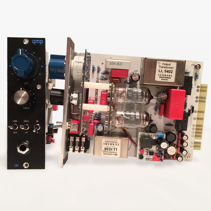
I finally finished up the build!  I have not powered up yet.  Can anyone recommend a good testing procedure?  Want to make sure things look good before i power on,  and i want to make sure the voltages are right before inserting tubes.  Thanks for any suggestions.

6Ho9qOC.jpg
 
Great build!

As far as testing... do a visual inspection first, and be careful when testing the B+ 

Make sure the MOSFET under the PSU is not touching the bottom of the PSU (or anything else).
Take a careful look for shorts on the Maxim chip, it is small.
When you measure the B+ voltage it is easy to short the test probe (I fried a Maxim that way).  I found best test points were before and after the jumper resistor under the bottom tube (but you can still short to the ground plane if you nick it so be careful).

My test procedure was to use cheap chinese 12AX7's as guinea pigs, and fire it up.  That was probably not the best way. 

I do have a simple suggestion though. Looking at your nice clean build I would like to point out that the filament power wires run directly under 120KHz power inductor on the PSU, and then touch the input transformer.  (Maybe not a good combination as the top and bottom of that inductor have the least shielding, and the input trafo has the most gain added to it's signal.)

Probably not a big deal.

The PSU is well designed, and does not need additional shielding, but I would re-route and tightly twist the wires.

Better practice (and routing used in Gemini's pictures) would go north then west between the tubes, giving the power inductor a wide berth.  And tightly twist the wires for good measure.

Nice looking front panel and knobs...
 
Wow.  So i finally got the chance to test/install and experiment with these.  I'm really liking the sound of them.  excellent.
I haven't run mics through them yet but tried them as inserts on various line sources.  Ended up using them on my overhead stem in a mixing session last night.  I really liked them there.

Also tried running drum bus through them... which i really liked also.  I have some vocal sessions to do so im going to through up a couple mics and try some different combos into these pres for vox.

Thanks.  great project.  So glad I finally got them into service!
 
qmp audio said:
I finally finished up the build!  I have not powered up yet.  Can anyone recommend a good testing procedure?  Want to make sure things look good before i power on,  and i want to make sure the voltages are right before inserting tubes.  Thanks for any suggestions.

Looking awesome !
Anyone having some pcb's/metalwork left of the gix kit? I'd be very interested.. ;)

greets
weiss
 
Heh, I want to build this preamp too! Will it work with ribbon mic that has 250 ohm impedance?
I wonder, may be author can share drawings, pcb layout (for printing), or the files that he send to the company which had print the pcb?
I will be really grateful for this.
 
Merry Christmas all!

Just finishing off my pair.
First one will have Lundahl's  for both in and out.

Wondering what opinions were of a complete OEP build or using the Ed Anderson input?

Cheers and have a great holiday season.
Mac
 
Anyone have any PCB's for these, or know where I might source some? I have built the 2U rack version (original Gyraf GIX) and would love to put a couple of these into my new 511 rack.
 
I just (finally!)  put together my pair of GIX 51X units. Unfortunately, BOTH HV boosters are not working (only 24V output). I am definitely an SMD noob, but I used a DVM to check all the connections (e.g. pins 1-8 on the MAX1771 to their corresponding components, etc.) I double-checked everything I could -- the diode is working, the MOSFET looks good.

Any suggestions on where to start? I have a 51X 'extender,' but my shop with o-scope, etc. is unfortunately in a different location than my lone 51X rack & PS. Sigh.
 
One thing is to check current across the rsense (smd resistor). If your MOSFET isn't grounded, it won't pull the inductor to ground and charge it. When the MOSFET turns off, the charge from the inductor is forced through the diode, into the hv cap.
 
Thanks, Rodney.
I re-flowed the solder joints on the MAX1771s and got both PS working. SMD ... bah!  ::)
They were both producing around 250VDC, so I had to fiddle with the FB resistors to get them down to ~240.

Both units are 'working' now, but output on both seems really weak.

A dynamic mic can only get to about -20db output with a loud 'hello' into the mic and both gains maxed, with slight distortion (as I'd expect on 10/10).

Using a guitar into the DI there is likewise a little distortion on 10/10, and the output signal only gets to about -15db.

The voltages on the 12AU7 tubes seem reasonable (240/84 on V2 plates, 160/81 on V1 plates). The tubes all test good on emission (I haven't tried them on the curve tracer, because that would require a bit of work currently).

I double checked and the both TR1s are A262A3A (1:6.45) and both TR2s are A262A2E (2:1).

Any suggestions what to check next?

 
Next I'd check feedback network. Make sure your values are correct. Try swapping tube positions, see what happens.

Also check through the official g9 thread, the circuit is the same, so troubleshooting carries over. The only unique trying about the GIX-51X is the form factor and the hv booster.
 
Back
Top