Build PICs.
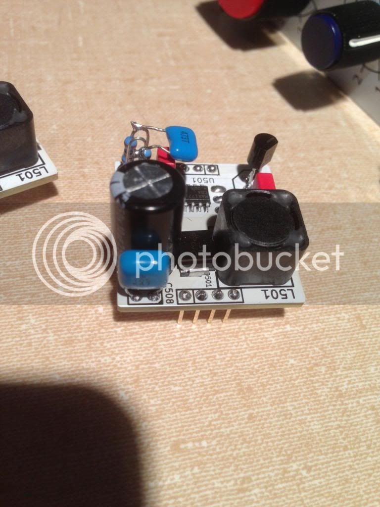
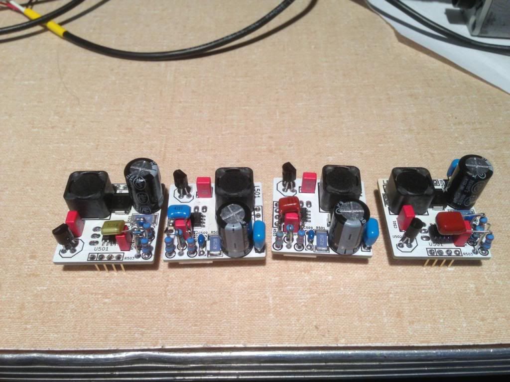
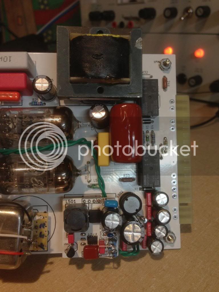
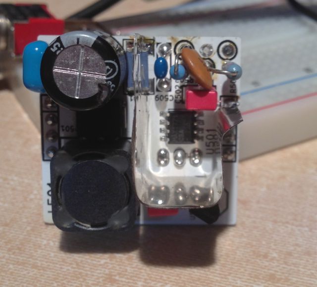
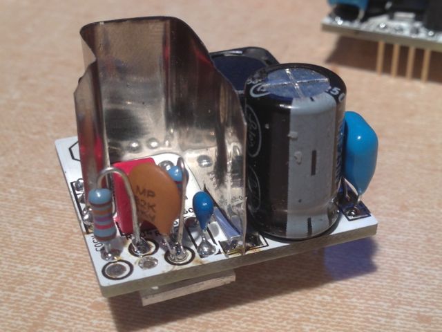
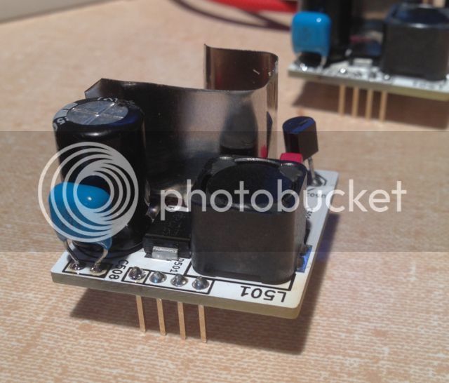
I got to use my hot air rework station to assemble these. I put the big inductor down first, because it takes so long to heat, but you really have to shift it to make room for the diode, so the big electrolytic fits (as gemini86 notes, but did i listen?) and I didn't, but I got it all on the card.
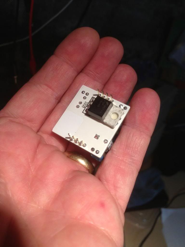
4 little High Voltage cards, with different bypass caps tacked on.
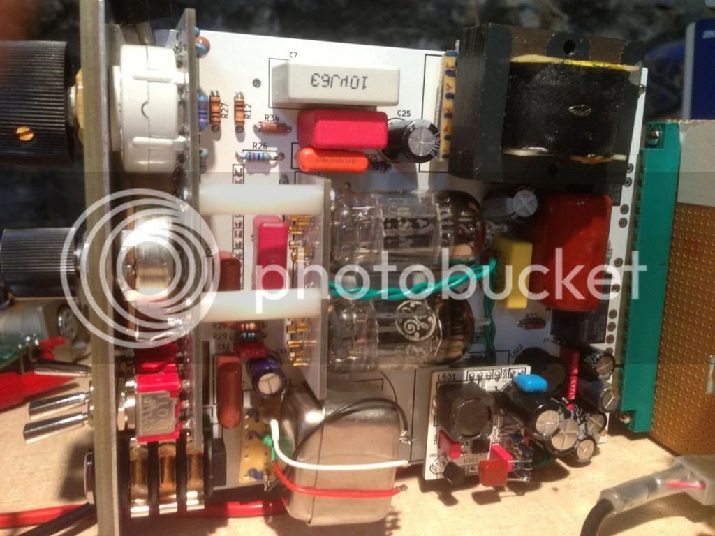
Card set up to test, I don't plan to leave these makeshift transformers, but I made Lundahl adapter cards for some scavenged transformers (and worked very well actually) 1:11 step up Altec on the input, 3:1 step down on the output, got good response all the way down to 20HZ with about 1 db rolloff, although I got some rolloff on high frequencies when the line switch was in LINE position, worked fine in MIC. Maybe the test generator? I will look into that.
I could permanently fit the output tranny but I would have to carve up the card... and it is such a pretty card, so not going to do that. The input however fits, and I might use that on some cards.
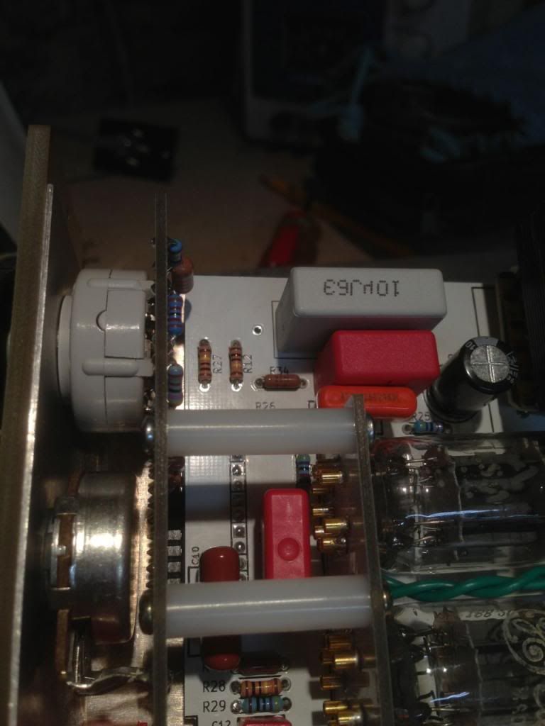
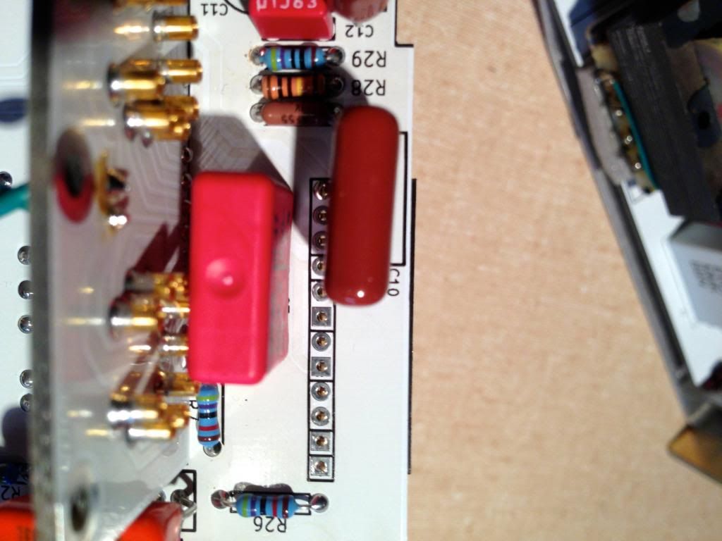
Note that I lucked out on the gain resistors. I had to use a 1/2 watt one in there, and it fit with some trouble, but only because of it's position. Some of them must be 1/4 watt where the main card comes close to the control card, or it won't fit. You can see one sticking up off the back of the control card.
Also note my choice of Polyprop for C3 fits, but I had to shift it, and I suggest using something smaller. Also you can see that I wedged in a 24mm output pot, works fine, and feels nice, I have the spec'd part on order.
Big honking 4.7uf Polyprop on output barely fits, I had to shift the electrolytic cap some (that cap has 250 volts on it so be careful with the leads).
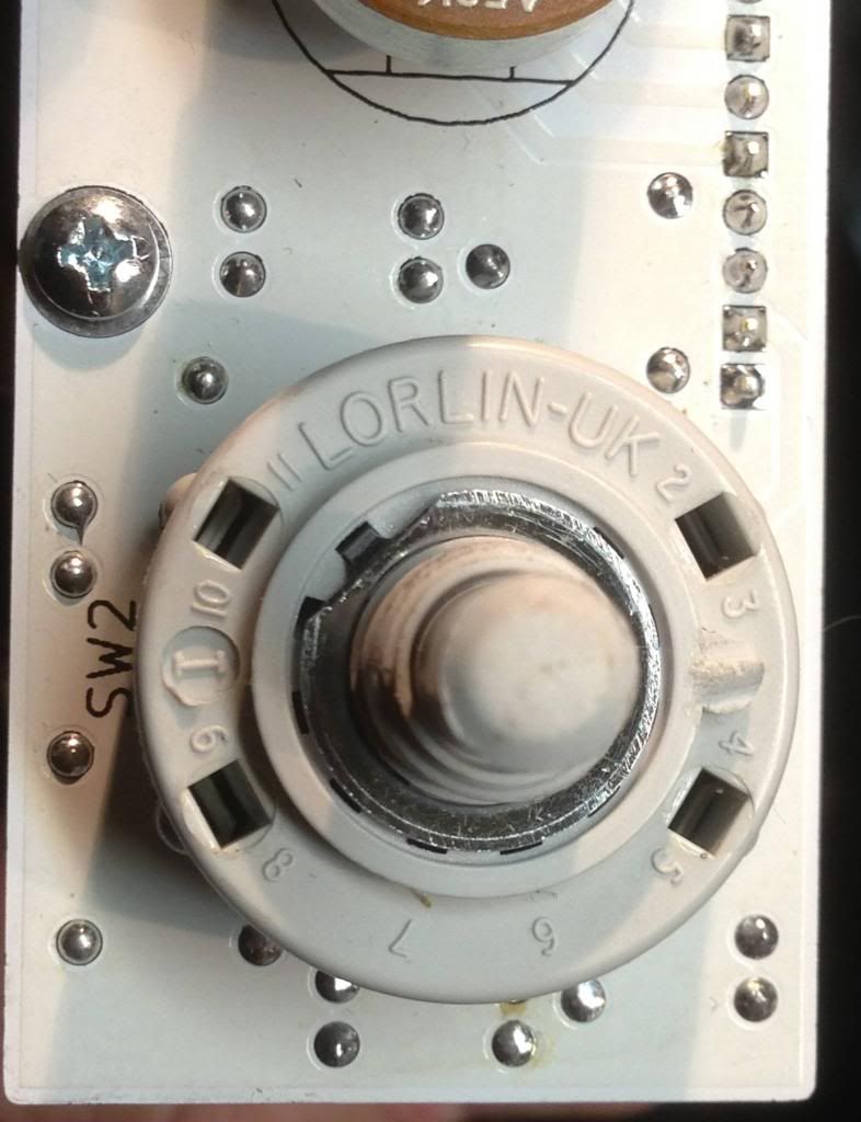
Set the Lorlin for 11 positions, 10 clicks or ticks.
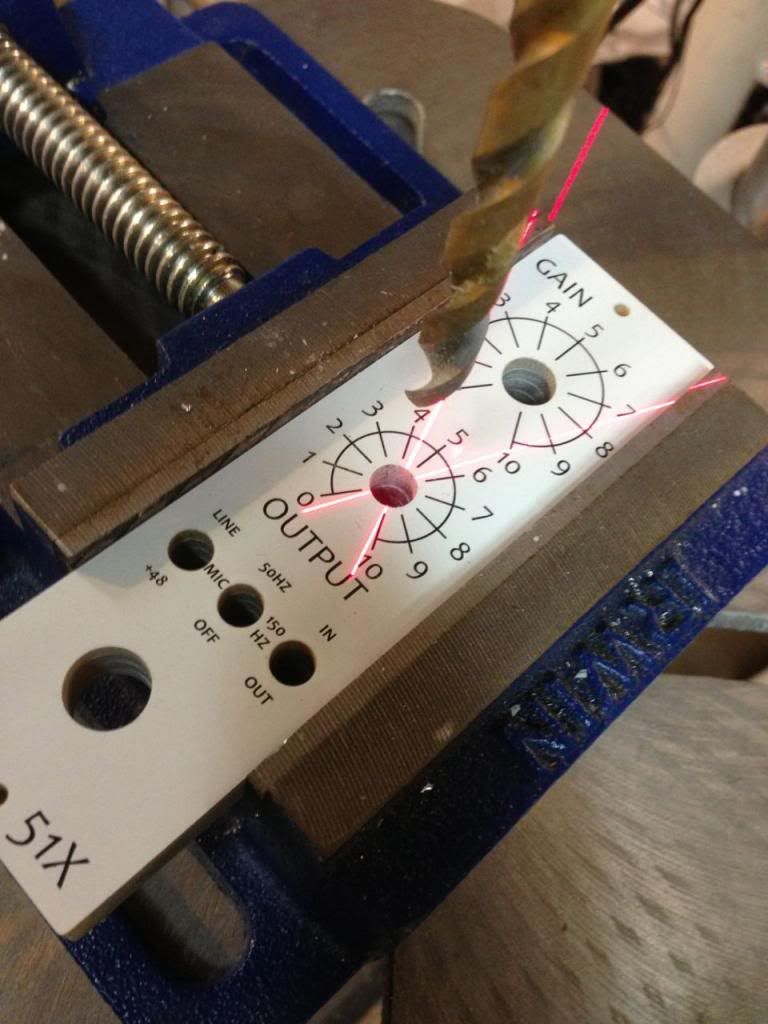
I needed to drill out the faceplate output hole, this may be because it is too small but it may be because I used a 24mm pot.
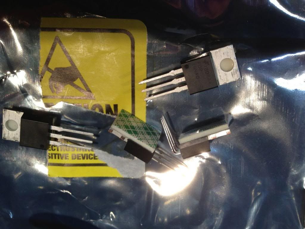
In insulated the back mounted MOSFET with foam tape, not sure this is such a good idea, hard to remove things once this is on, and it does soak up the flux cleaner. But it is secure.
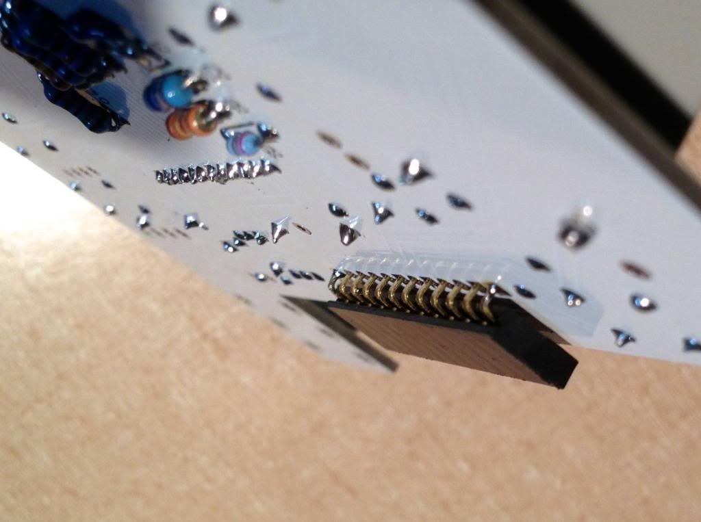
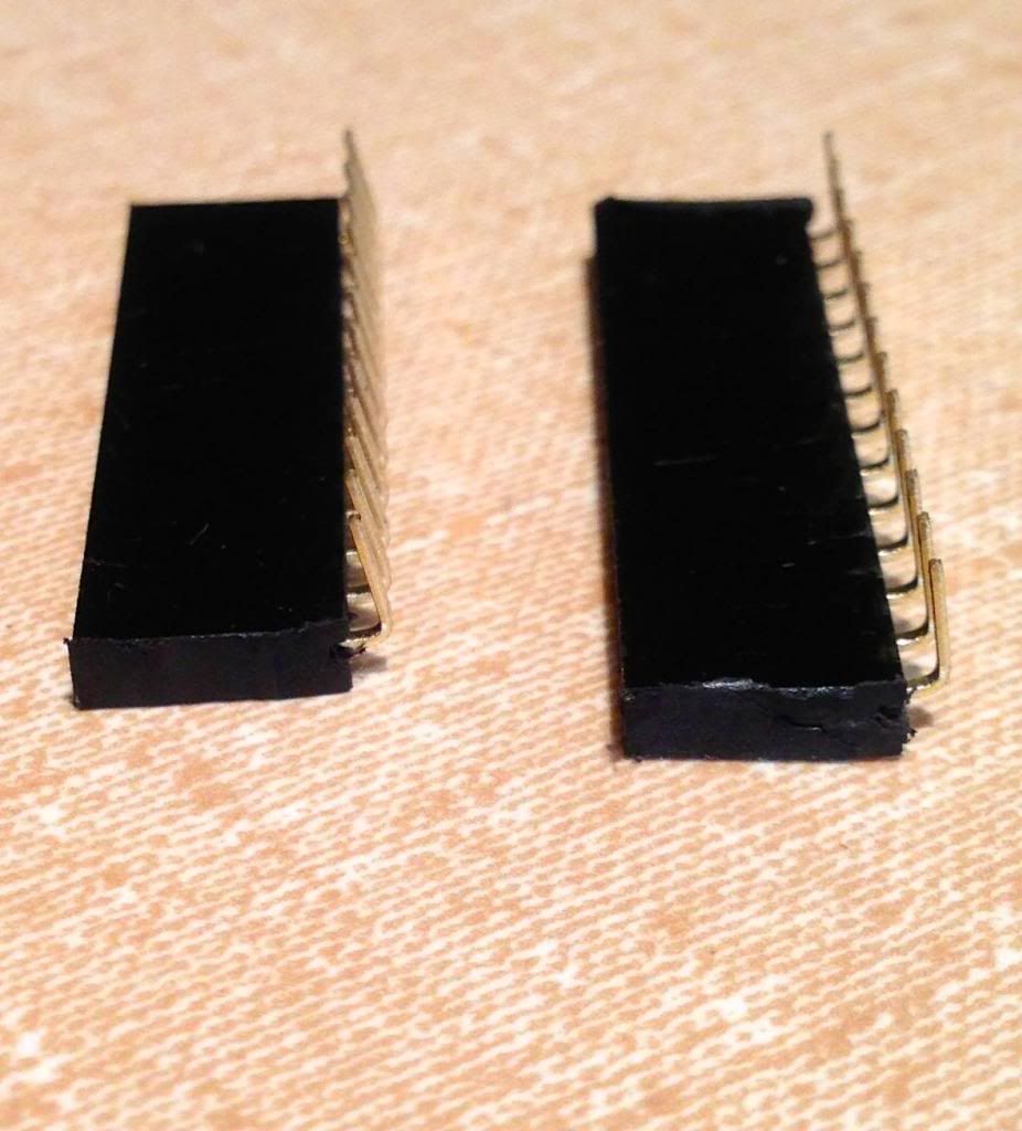
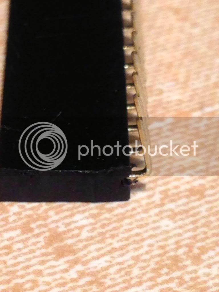
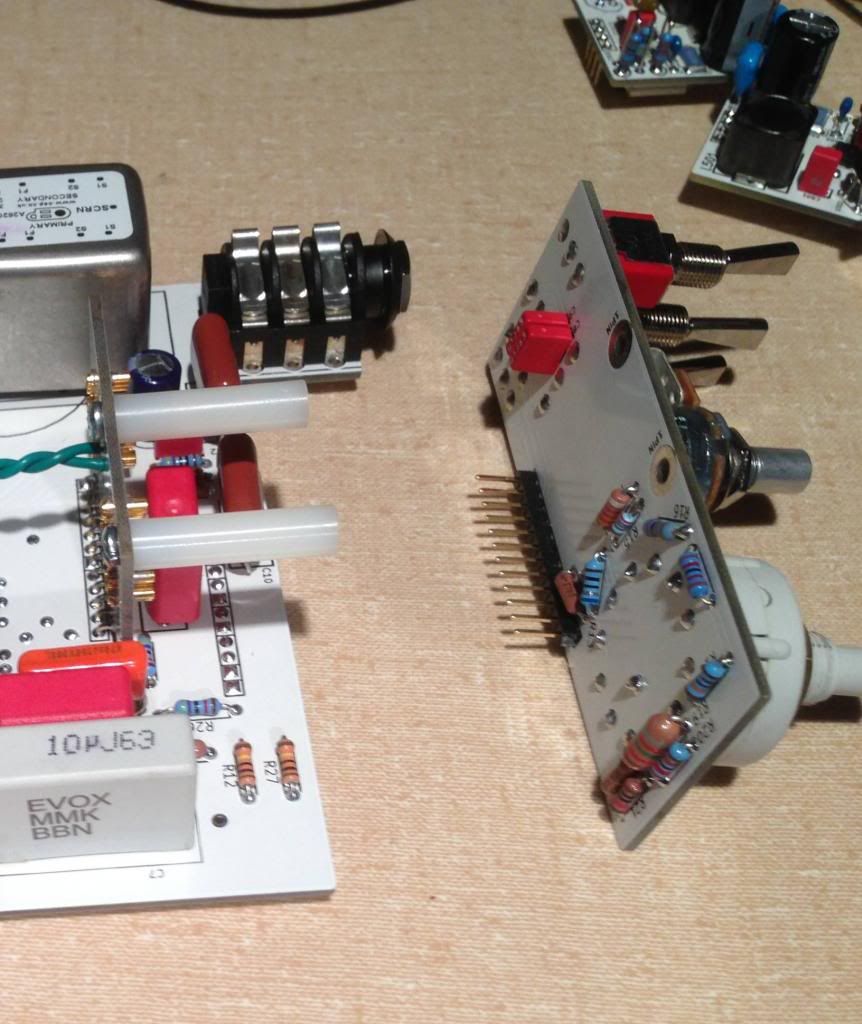
Here is how I mounted the socket for the board mating. Because my sockets were a bit too long i thought, I bent the bins a bit and mounted it elevated, which worked out fine (but lowers the above board clearance a hair, so if you are putting some tall transformer or cap on then lookout.
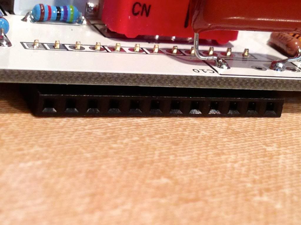
You can see the socket peeking out here from below the board. you can see my C3 is too big (and I had to bend the pins on it to keep it from contacting the tube sockets. Also note that C10 could interfere with soldering the bottom socket if you install it early (as I did).
Another view of the socket. Note C10, if it was a WIMA I would have had to remove it.
Bent pins on the socket, to help it stay back under the board, hope it doesn't mess up the reliability of the socket, not sure it was necessary.
Here is how it goes together, and with standoffs and screws it stay firmly supported.
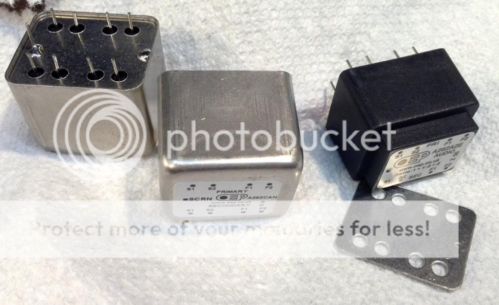
On the second build I used OEP's, and cans. The cans come disassembled, and I tacked to ground pin to the bottom plate and the plate to the case for solid grounding. Not sure it is needed. Note... label the trafo's or you might have to take em apart to see which one is input. Also not sure I am going to stick with these Trafo's they were cheap (15 bucks a piece) but I am getting really wacky stuff with the low frequency and the frequency response I am measuring is not very flat. Maybe I need to terminate them differently? Should these work down to 50 Hz in a reasonable sine wave at 0.5Vrms? Mine don't ... I might have some other problem.
Also NOTE on the BOM the Input and Output are switched. They are correct on the schematic. The A2E is output the A3E is input.
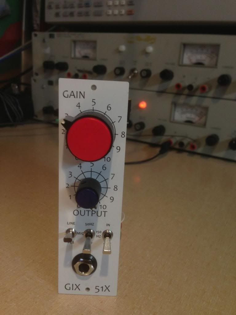
It looks nice, even with Radio Shack knobs.


