[BUILD] GIX-51X tube preamp

GroupDIY Audio Forum

Help Support GroupDIY Audio Forum:

This site may earn a commission from merchant affiliate links, including eBay, Amazon, and others.
One other thing.  When the Datasheet says "maximum switch on time", and "maximum switch off time" I don't know which thing "on" is and which thing "off is".  Does "on" mean the MOSFET is conducting?

The reason I ask is that currently if you look at the Drain pin on the scope it is "240" Volts ish for 1 u-sec, the "0" volts ish for 9 u-secs.  So that is "Off" for 1 u-sec, and "On" for 9 u-secs.  The minimum switch off time is 2.3 u-sec, so either we need a smaller inductor or more load (or I have swapped what On and Off mean) or maybe C509 is interfering somehow.

In any case I thought I would let you know it is "not conducting" for only 1 or 1.1 u-Sec which is half the datasheet minimum.  This is my first foray into switching PSU's and while I am fascinated, I am also befuddled.
 
The switch is normally off, on when at least 10V is applied to the gate.

I had previously tried 470pF with no luck, but that was the old layout and I don't remember what the feedback network was. Still probably worth trying.

In some areas the datasheet if very vague. They're assuming that we're using it for probably a max of 24V out. We're kindof in uncharted territory with this chip. The max668 chip, however, is used as a 48V phantom power converter on their website, and their tech support engineer was steering me in that direction (he seemed to not want to help me with making this part work.)

You may be onto something with the inductor being over spec'd. I hadn't thought of that as a problem. I got that value from tech support, but the datasheet says:

"inductor values range from 10μH to 300μH.
22μH is a good choice for most applications. In applications
with large input/output differentials, the IC’s
output current capability will be much less when the
inductance value is too low, because the IC will always
operate in discontinuous mode. If the inductor value
is too low, the current will ramp up to a high level before
the current-limit comparator can turn off the switch.
The minimum on-time for the switch (tON(min)) is
approximately 2μs; select an inductor that allows the current
to ramp up to ILIM.
The standard operating circuits use a 22μH inductor.
If a different inductance value is desired, select L such
that:
      VIN(max) x 2μs
L ≥ -------------------
              ILIM
Larger inductance values tend to increase the start-up
time slightly, while smaller inductance values allow the
coil current to ramp up to higher levels before the
switch turns off, increasing the ripple at light loads."

My math is not so great. So I don't know how to calculate L. I do know that 100uH was too little, and caused the controller to just lock the switch on and suck current through it. I wonder what backing off to around 200uH would do.
 
Some notes from my build:
Update:  More incorrect info.  I have now measured noise and there is no discernable difference with the screening can I built, except if you use the Cinemag input Trafo, which is very close to the HV psu, for the Lundahl and OEP (with screening can) input trafo's the noise is the same with or without my screen on the PSU


Update:  I had a lot of bad information in this post, I have updated it to correct that information.  The supply does regulate fine, the problems I think now are in filtering and in induced currents in the ground strap of my oscilloscope probe from the radiation of the power inductor.  See my more recent posts for what parts I ended up using
The G9 is a tried and true, this GIX works, but the B+ supply  on this design needs some fiddling. 

In the end the fiddling I did was to improve the filtering.  That is specified in a more recent post.

When the HV comes on it comes on faster than the heaters, and the voltage exceeds 250 Volts.

You can fit 350V 10uF on the HV card (there are 10mm diameter ones, anything up to 19mm high fits). The voltage surge above 250 Volts at the tubes until the heaters come one and if you build it with a resistor instead of a HV jumper you get a voltage drop. Update: I put the values I ended up using in a more recent post.

A startup delay would be cool, I will look at that. 

If you want to run "In Phase" and Line (not mic) the relay cois are both powered all the time. R33 and R34 spec'd at 100 putting the relays exactly at the OMRON maximum rated current, can be 120 to 140 ohms and is better.  A lower current relay is also available.

I used right angle SIL square pins to mount the tube board, they are stiffer that way, which is nice because the tube holder gets stressed upon insertion, but you have to pull the black plastic part off the off the SIL header after mounting them on the tube board, which is easy enough if you go slow, or you warm it with a heat gun.

The total current draw on POWER ON is 0.5 amps between +16 and +24 combined, so I am not sure how many you could turn on at once in one rack, it depends upon your PSU.  Again a startup delay might help.

I shielded the HV card, not because I think it will quiet the power, but because I am worried about the magnetic radiation from the inductor. The input transformer in particular is susceptible to such stuff. Here is a link to a video that shows the amp noise varying in response the nearby objects (first my finger, but only within an inch of 270Volts!) then the oscilloscope probe.

http://s1221.beta.photobucket.com/user/Bruce0/media/G1X%2051X/IMG_1542_zps9f9d1029.mp4.html

It turns out that the shield improved my performance because it prevents the oscilloscope from picking up the radiation, so it really wasn't improving the power supply.  However I plan on using the shield because I don't want it effecting other components or other 51x modules.

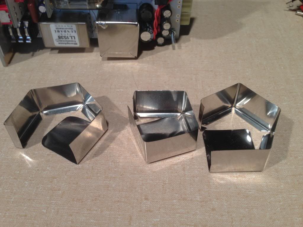
Here is the shield I put in place, it is designed to fit the HV PSU exactly, and it is NOT SQUARE.  It tack solders onto two of the pins which are grounded.  I later modified it to bend it away from the HV Out pin, because it is really close to that 262 V and it is grounded.

I can provide a template, for cutting your own shield.  It folds up from one piece and then is tacked in two places with solder.  I made mine out of mumetal.

IMG_1548_zps451c6bf5.jpg


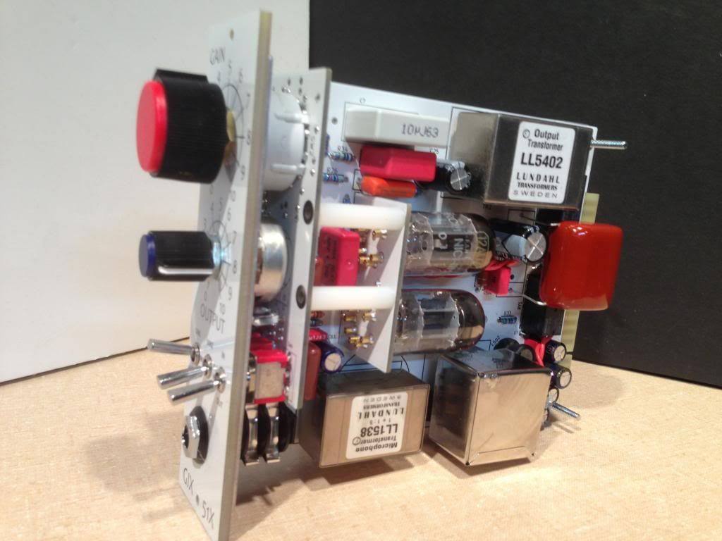
I hot glued the output cap to the top of the relays, which seems pretty secure, and was the only way to fit the polyprop caps well. It also leaves room for a 22uf cap there.  The tube rubs against it when sliding in or out, but then sits clear of it.  The input Lundahls seems upside down but i think that is right.

IMG_1547_zps5c695dcc.jpg


Thanks again bruce for all the help. You seem to be able to wrap your head around switching circuits better than I.

That shield you've made is awesome. Any measurable improvement over unshielded? I've yet to find noise contamination on the output of my build, so I haven't invested much time into improving shielding for the converter. Future designs will definitely feature a fully shielded converter, in case it's ever an issue.

I'll be updating the BOM and schematic to reflect the converter parts changes.
 
Updated table with more data

The build as designed and specified works fine!
I got a personal message from one builder concerned that he was biting off more than he could chew, and I realized that my obsession with PSU noise might be disruptive.  So by all means build this lovely project, it is really a nice bit of work. The "Stock Build" works fine.

Most of us with GDIY 51X racks have gone to the trouble of building big linear supplies and keeping switching noise out of the system, and this HV supply is necessarily a switching supply, so what I am trying to do is to mitigate any effects of putting this in my GDIY 51X rack, but I admit most of the noise I have detected so far has been on the bench and NOT on a set of speakers.

The relatively high noise levels in the B+ power supply is mostly not audible.  There are four noise sources I am working on:
[list type=decimal]
[*]Fixed by the "Rodney Cap" mentioned here: http://www.groupdiy.com/index.php?topic=51020.msg649756#msg649756. This is a nearly triangular Low Frequency Oscillation in the 60Hz to 100Hz, very audible.  This goes away with the Rodney cap (which BTW can be a low voltage cap 6V or more I used 50V)
[*]High frequency noise of the same frequency range as the Switching Frequency.  Generally I want this frequency to be higher and variable (white noise), so that the noise is farther from the audible spectrum because I am concerned about harmonics.  This noise can be heard as a very low level hiss and whine (with the gain at MAX) I have heard it in the stock build Update: I think that this was radiated noise being picked up by my signal generator..

[*]Noise induce into other components by the radiation of the inductor, which is substantial. This is a high gain preamp and is susceptible to radiated noise. Depending upon build, and transformers, and caps I have heard this feedback as I move objects closer and farther from the inductor, and this is why I have been working on shielding.  That said, some of the PSU builds don't have this problem. In this video you can hear it yourself, just recorded on my phone. http://s1221.beta.photobucket.com/user/Bruce0/media/G1X%2051X/IMG_1542_zps9f9d1029.mp4.html
[*] A gentle LFO at 4 to 7 Hz. :-X. Note: This LFO does not exist, it is noise induced into the oscilloscope probe from the field of the power inductor
[/list]

I don't have enough experience with the G9 to have an expectation with respect to noise level.  In fact I have a rack mount G9 I am building to try to find this out, but i have been delayed by the Par-Metal puzzle.

I bought an assortment of inductors and Sense resistors, and I have fried a couple of MAX1771's (ouch) and here is a summary of my testing, and some test data:

I have a longer writeup of this, but in general it is a balancing act. Smaller inductors generally lead to higher frequencies but if they are too small the regulation feedback pin never gets near enough to 1.5V to trigger, and if it gets too far out of whack it defaults to the maximum (16.5usec - 46K Hz) or sometimes to non-oscillating continuous mode ("Amplifiers do, Oscillators don't"). Larger Sense resistors generally increase frequency but to a point, but interfere with regulation, and tend to produce consistent frequencies.  I am searching for a balance of high frequencies (100kHz to 300kHz) that vary like white noise.

Update: Note that the ripple current increases as the inductor size decreases, and can get to be a very large current.  It is better to use larger inductors if you can maintain the voltage and frequency.

All of these measurements are taken with the HV jumper configured as a 750 Ohm resistor, and the regulator set for 255V.  All tests from J onward had the Rodney cap installed (.1uf 50V MLCC)
IDInductorSensefrequencyComments
A100uH.06226kHz to 35kHzMaintains 255V, not warm
B100uH.06234kHzMaintains 255V, not warm, don't know why A and B are different
C68uH.06246kHzSometimes goes to continuous mode 23V sometimes produces 140V, MOSFET and Inductor get hot
D22uH.040Unrecorded62V, Hot MOSFET and Inductor
E33uH.062Unrecorded75V, sometimes 23V
F56uH.062Unrecorded110V
G22uH.120>300kHz234V unstable output ( Rodney cap might fix but voltage is low, and the chip is not designed for above 300kHz)
H47uH.120250kHzMaintains 255V,  Hot MOSFET and Inductor
I56uH.160 UnrecordedMaintains 233V, Stable but low, Warm but not hot
J68uH.120130kHzMaintains 255V,  Not really warm (acceptable), RC (Rodney cap)
K47uH.160287kHz230V,  Warm inductor and MOSFET
L100uH.160148kHzMaintains 255V,  (No notes on temperature, but not hot) RC
M100uH.12096kHzMaintains 255V,  (No notes on temperature, but not hot) RC
O330uH.250101kHzMaintains 255V,  (not hot) RC (stock)
P1000uH.250Reads 43kHz must be 46kHzMaintains 255V,  No notes on temperature RC
Q680uH.25058kHzMaintains 255V,  (No notes on temperature, but not hot) RC
R180uH.250>200kkHz248V (low) RC
S180uH.160141kHzMaintains 255V,  (No notes on temperature, but not hot) RC

Update: see my later post, I believe the smaller inductors are a bad idea.  There are significant differences in audible noise and measured PSU noise,  but my test environment is not controlled enough yet to sort that out, and some of it has to do with shielding, transformers and individual tubes. I will report back after racking one and measuring noise and a listen.
 
I will I am still changing values. 

The BOM as specified works fine, but I am still testing. and will update values as soon as I am done.  We have a blizzard here now, and I will have a bit of time while we are snowed in.

One thing I have discovered is that for this high frequency switching PSU work I need to use a different tip on my oscilloscope probe, otherwise the ground wire makes a loop that picks up more signal than the signal that is there.


It'd be nice if we had a Rolls Tubule (or similar) to study.  These sorts of supplies are an area of total ignorance for me.  Thanks to bruce0 for all the data observations. 
 
+1 thanks Bruce for generously contributing feedback to this project--nice to see an old guru learning new things.
 
emrr said:
It'd be nice if we had a Rolls Tubule (or similar) to study.  These sorts of supplies are an area of total ignorance for me.  Thanks to bruce0 for all the data observations.

I did reach out ot maxim IC for some help, but a lot of my layout choices were made by studying other gear, including the Sound Skulptor mp66. They have documents for it on their site.

okgb said:
The roll  500 pre uses a 12dw7  , so I presume one tube only ,  going for about a grand

The roll unit has to function within the VPR power specs, so they can't use the current that two tubes need without burning two rack spaces. I also imagine they outsourced the design of the switching supply and had to buy up a couple thousand units to have them produced, which jacks up the price a lot.
 
The pictures of the Rolls don't look like they have any custom modules, but it's hard to say. 

I hadn't looked at the MP66, interesting piece.  I notice there's no apparent spec given for one of the PSU inductors, and they have a fitted shield around the whole thing. 

I'm gonna talk out my ass for a second and bring up the parallel film caps in the PSU.  Are they creating an inherently good condition, or is it possible they might be lowering ESR at a given high frequency to a point that destabilizes?  Disregard as needed! 

I see Mouser has a few 12V:200V/300V DC-DC converters now, at $123 apiece(!). 

Watching with interest....
 
Well, there's a HF noise on the line that should be removed, and there needs to be at least one ultra low ESR cap on the output to deal with that.

I think the number one problem we were having before was a wrong inductor size. It seems the 330uH was too big, and was causing a condition where the controller was pulsing at a very low pulse width. A 100uH inductor allows the pulses to widen out and get the fb pin doing all the regulating work. Bruce has done a great job documenting what works and why. The current sense resistor and the inductor are two component that must work together.
 
Parts
I did my final build with the following:

L501            330uH (as originally specified) (Updated)
Rsense          0.250ohms (as originally specified)
L503            1200 uH Bourns 652-RLB9012-122KL
NEW CAP        Tack a .1uf ceramic capacitor (350V) between the end of that inductor and the HV out on the boost converter on the back of the board.
HV Jumper      200ohms ( I used a 1/2 watt, I don't know why Gyraf specs the R31 at 2 watts, it sees 5-7 mA and has a 5 volt drop. What am I missing tube guys?) (update)
C507            22uf I used EKXJ351ELL220MJ20S, it fits fine.
C25            350V 22uf also fits EKXJ351ELL220MJ20S (update)
C25            350V 10uf 350V 10uf, if you want to be true to Gyraf design 647-UVY2V100MPD (HV card exceeds 250V on startup)
C503            350V 10uF 647-UVY2V100MPD (HV card exceeds 250V on startup)
C508            450V 1uF version RDED72W105MUE1C3A (HV card exceeds 250V on startup)
R502            300,000 ohms
R504 + R503    A single 1800 ohm resistor (measure these with a DVM, a small difference on this part makes a big difference in voltage)
R33 and R34    120 to 140 ohm to reduce current use
C509            I built mine with this omitted.  I found it makes no difference. (Update)
Shield          I put a shield on my HV boards, if you want I can upload a pdf template of it.


You can use a bigger resistor for the JV jumper and get better filtering, but I find it is fine for the noise frequencies present and it keeps the supply impedance low.

The smaller inductor was my bad idea.
I have been reading up on boost converters, and it turns out the ripple current produced by the power inductor is related to it's size as well, and on some of the inductors I was suggesting was getting as high as a few amps! (actually limited by saturating the inductor)  That's why they were getting hot.  We want to keep that number lower so that the ripple voltage is low and so that we don't get above the rating of the filter inductor (L503).

Last night I modeled our boost converter using the cooper and bussman guidelines document, and this table is a summary of that:

Inductor Vin Vout Iripple
330        24 245  0.410
  68        24 255  1.998
180        24 255  0.755
330        24 255  0.412
680        24 255  0.200
820        24 255  0.166
1000        24 255  0.136

Note that the ripple current on my smaller inductors is much higher than the rating on the L503 inductor which is around 370mA.  Furthermore the ripple current makes ripple voltage in the B+ voltage (we don't want that). That voltage is related to the ESR of the CAPs used to store and filter the pulses.

So really we want a larger inductor, but I tried them today, but I couldn't maintain high frequency, and 255V except with the 330 inductor.  (The current ramp up on the larger inductors is slower, and the result is more efficient, but not enough energy get's stored if we run them at high frequency).

Actually you get a really quiet supply that works with a 0.120Ohm sense resistor and a 1000uH inductor, and it uses less amps from the GDIY 51x power supply, but it runs at 56Khz.  It has lower ripple by half, and it sounded quiet. 

The 330uH Inductor with the .250 sense resistor is good.  It may be we can use a larger inductor, I am going to try out the next size larger and see if it works, but 680uH is too big.

The improvement that can be made is in the filtering.  All the "design tips" documents on boost converters say you need to put an LC filter after the boost converter.  In the schematic, that LC filter is formed by L503 with C507/C507.  The general recommendation is to have the LC filter frequency at 1/10th the boost converter frequency, and this is where we have diverged from the recommended design. Our boost is running at around 15K, and our boost is running at around 100-120K.

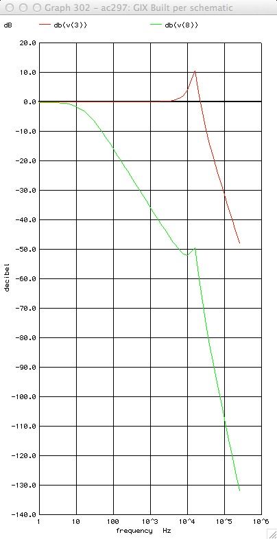
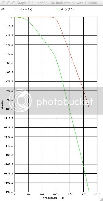
Here are Spice models of the frequency responses at the Driver and Gain stage anode for the original schematic and one using the filter changes specified above. Red is the Driver Stage, Green the Gain Stage.
HVPSUFilterperschematic_zps0b6b0448.jpg
HVPSUFilterperthispost_zps12536817.jpg


Note: There are other LC filter arrangements that work, but this one fits best.  You can use much smaller inductor like a 22uf axial cap which fits pretty well across the top of the relay, but you still have to bypass it with a low ESR ceramic and that fits on the back,  so I chose this approach.  If anyone wants I can provide the various options.


Mea Culpa section:

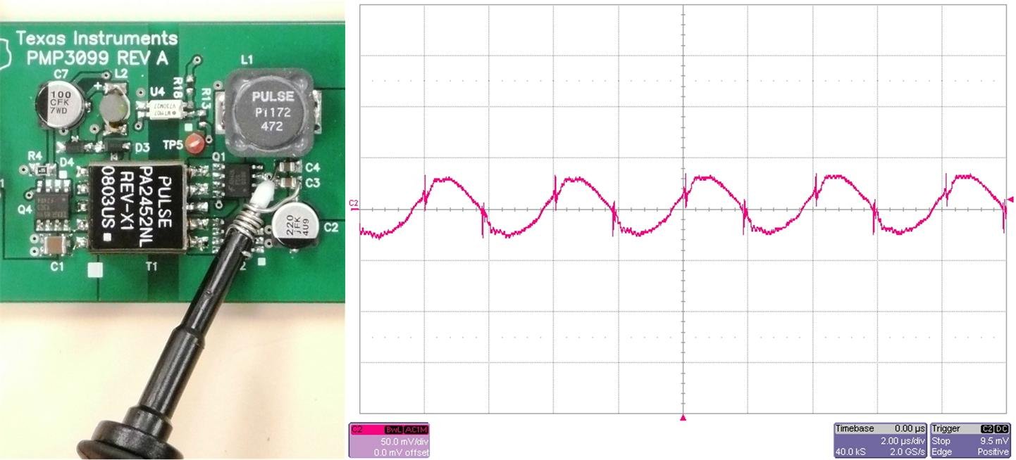
#1) The LFO oscillation I noted in earlier posts DOES NOT EXIST! it was an artifact of using an oscilloscope probe with a ground wire and clip.  When I shorten the ground wire and clip as shown here, the problem goes away.  This is just a bit of bare wire wound around the tip replacing the ground clip:
Figure_2.jpg


#2) The shield is not strictly necessary.  What the shield was doing was preventing my scope from picking up the false signals that I was interpreting as LFO oscillation.  But the field is strong and I am going to use a shield out of an abundance of caution.

(There should be a sheepish grin icon!) ;D  Sorry.

Bruce
 
Bruce, I'm a bit fuzzy on where this new inductor goes?

bruce0 said:
NEW CAP        Tack a .1uf ceramic capacitor (350V) between the end of that inductor and the HV out on the boost converter on the back of the board.

Are you just hanging another .1uF on the output or is this after L503?
 
gemini86 said:
Bruce, I'm a bit fuzzy on where this new inductor goes?

bruce0 said:
NEW CAP        Tack a .1uf ceramic capacitor (350V) between the end of that inductor and the HV out on the boost converter on the back of the board.

Are you just hanging another .1uF on the output or is this after L503?

Well the inductor replaces L503.  I updated the post where I said L502, sorry for the confusion.
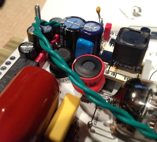
Note: In the picture and only for test, L503, and L501 and the HV jumper resistor are mounted on long lead's, tacked on. This is so I didn't have to keep soldering and unsoldering the boards which would surely have ruined them by now. For a build you should mount these properly although you can see that the inductor is a close fit and may need to be angled depending upon your choice of part.  (Also note C28, the 48Volt filter cap, is a 63V 100uF panasonic which I squeezed in). You can also see the Blue 450V C508, and the 350V C503, and the tacked on Rodney Cap.

PositionofL503_zpse67517a3.jpg


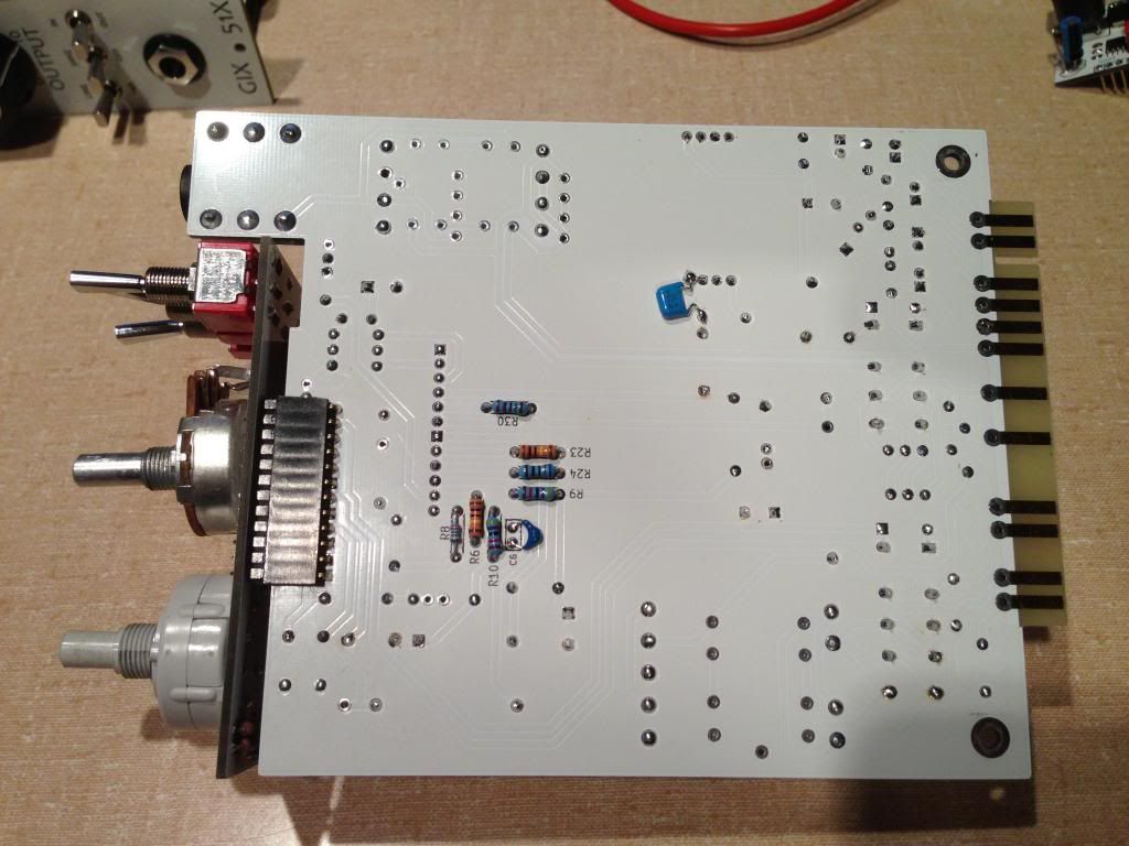
The new cap goes on the back of the board. 

IMG_1762_zpsc66096ba.jpg


As far as the part selection for that inductor see the note at the bottom.

All this L503/NewCap filter does is lower the filter corner down to about 1K, and puts it 40dB down at 13K where before there was a 10dB peak.  See the compared Spice model plots in previous post. The 8ohm HV jumper (I used 8.3 ohm that I had lying around from discrete opamp builds) makes an RC filter with C507 that smooths out the peak on the LC filter.  You can put more RC filter there, see my note at the bottom.

So instead of Boost Converter->LC Filter->Anode. you now have Boost Converter->LC Filter->RC filter->Anode.

In the MP 66 Schematic there is a 10uH/22uF LC filter (L3/C31) filter that does the same thing followed by a 2.2K/22uF RC filter  (R30/C17) (which is easier to fit without API format space constraints) which is down 60db at 10K Hz, and has large voltage drops and current limits.  By omitting and equivalent to C31 and R30 on that schematic the GIX-51X essentially runs no RC filter to the driver stage and has a 16.2K resonant peak (as seen in earlier posts).  All the boost converter guides say you have to run an LC filter after the converter, you can use big F small H, or big H small F.  The latter fits better as a retrofit to the GIX-51X.


LC filter part selection: You could find an axial inductor that can handle the .41mA ripple, but probably not that short.  You could take a long axial and mount it vertically (like the resistors on the HV board) and it would fit but a lot of the axials seem to be low current.  The one I tested with is a rewound version of an extra L502 part I had ordered (the 47uH one).  I rewound it with about 7 feet of 32 gauge magnet wire to replace the 22 gauge that was there,  pulled off wire till it measured 995uH, then soldered on leads and mounted it (see picture).  I had to lean it away from the HV board so it would not contact. 

One thing you may need to be concerned with is Q factor, which i frankly don't really understand.  Some of the Boost Converter notes mention the following fact.  This filter will filter the same frequencies that are "seen" by the FB voltage divider, so a "High Q" filter (I think this means a steep filter) may interfere with regulation or cause some problem.  I did not have a problem with that, but I don't really know the Q of my Inductor (I am thinking it is about 50).

More RC filtering: I put an 8.3 ohm resistor in the HV jumper. A larger resistor in there fits easily and dramatically improves the RC filter, but causes a bigger voltage drop. I saw 5 volts drop from a 750 Ohm resistor so there is about so it must be around 8mA or so.  If you do that you need to run the HV card above 250V, which works fine (R502,504,503 of 300K, 1500R, and 282R worked perfectly with a 750 Ohm HV jumper).  Do that and you must run 350V caps for C503, C508, C509 and for that matter C507 and C25 which I recommend anyway because the boost converter as originally spec'd always exceeds 250V on startup until the heaters warm up.  Those parts are available and do fit, C508 is RDED72W105MUE1C3A where you have to bend the leads because it is a 5mm LS part).  I put the smaller filter there because I couldn't measure an improvement with more, and it would allow folks to run at 250V if they already bought all the parts (albeit exceeding ratings briefly on startup).
 
bruce0,

Thanks for sharing your findings.  Are there any other limits on the inductor we should be aware of when sourcing?  Max DC.current etc?

Thanks,
Ian
 
irfrench said:
Thanks for sharing your findings.  Are there any other limits on the inductor we should be aware of when sourcing?  Max DC.current etc?

Thanks,
Ian

Ian:

I am out of my depth when sourcing the part, but here is what I have pieced together.  Someone with knowledge of magnetic components might provide much better advice:

1) Q Factor: No idea.  But based upon your question I read up and I think a higher Q factor is the combination of high uH and low DCR making the filter more "specific" to a frequency and raising the amplitude of the response peak at the corner frequency ( And the peak could trigger the feedback in the MAX1771 that regulates voltage, so if you have trouble maintaining voltage a high Q factor in the filter could be the problem).

2) Current: The Ripple Current using the 330uH inductor models out at 410mA, but I have not measured it.  I think that is what the part is exposed to.  The load current is in the order of 8mA, so 418mA.

3) DC Resistance: I think lower raises the Q factor, but in general I think lower is better but you will find you don't have much choice, the size, core material, turns and wire size are all pretty much connected mathematically. My test part would spec 1700uOhms (milliohms) or 1.7 ohms max but measured at 1.3 Ohms. 

4) Size: It needs to fit where L503 fit. Lead spacing is an issue, Fitting next to the HV card is an issue, If it is too tall it will stand up next to the Power Inductor (L501) and that is radiating like crazy even though it is a shielded inductor and I don't know what kind of mutual inductance issues you might get there.  In my test setup, as you can see in the picture, both of those inductors are raised up off the card, and I didn't have any problem with interaction that I could detect.

5) Henrys:  I chose 1000uH.  A smaller inductor will raise frequency where the steep part of the curve starts, but might be fine.  My corner models around 1kHz corner, if you use a 470uH inductor that moves up to 1.6kHz, it would probably be fine too.  My choice of 1000uH was because it is hard to get a higher value inductor that will handle the current and fit, but any value 300uH and up would probably be fine.

6) Tolerance doesn't matter obviously

7) SRF: Self resonant frequency is also a limiting factor, not sure but I certainly think you want this in the mhz range and up.  I am not sure of my measurement tools at high frequency so take this with a grain of salt, but I see noise at just about 1mHz range so you want SRF to be above and far from that.  I think the part I made had SRF around 1.6mHz but again this is a guess.

8 - General: Not sure if it matters but what this is I think is called a choke but also seems to be called a fixed inductor.  Chokes and Power inductors seem to be a special case of fixed inductors.  I don't think you want a power inductor although I think they might work fine (I don't know how they differ).  I don't know if shielding would hurt or help, I think it couldn't hurt but I chose unshielded because most fixed inductors were.

Thus exhausting my "knowledge and conjecture" on the topic.


okgb said:
Bruce O , can you update your bom  ?
Here is an updated BOM as I currently have built it.  Doesn't spec L503 or the New Cap, I ordered some choices from mouser and will try them out tomorrow, and post what I use.

File is a tab delimited spreadsheet file, can be imported as tab delimited
 

Attachments

  • Partial Mouser rev 5.txt
    4.2 KB

Latest posts

Back
Top