Hi guys,
I'm currently doing my research for building a stereo Altec 428A preamp with an external power supply. Right now I'm drawing some layouts and I got a couple of questions:
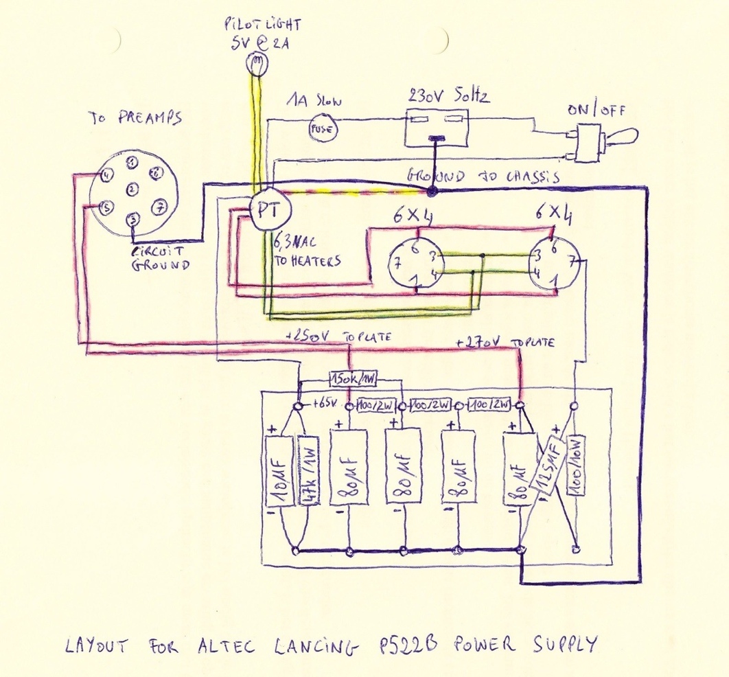
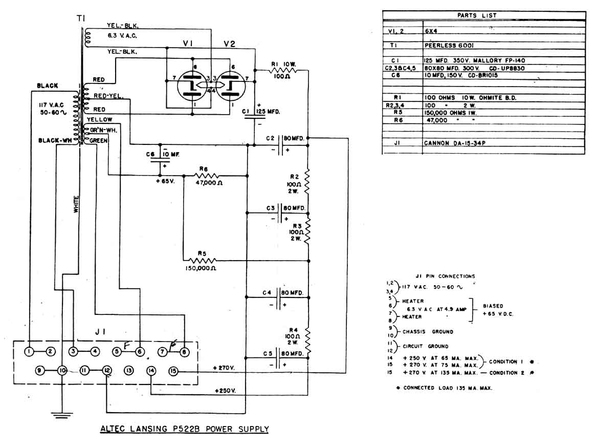
- here's the schematic of the original P522B power supply: http://www.waltzingbear.com/Schematics/Altec/Altec_P522B.JPG
does anyone know what happens there with pin 7 of the two 6X4 rectifier tubes? Is really connected to the filament heaters?? Can anyone tell me why?
- anyone any suggestion for a power transformer? I would need a universal primary that takes 230V. The thing is, in the original schematic there are two seperate filament wirings. One that goes to the two 6X4 rectifier tubes and one that goes to all heaters in the preamp tubes. Does anyone know why this is seperated in the first place? And do I really need seperate wires like this or can I use just one pair and go from the 6X4 heaters to the preamp tube heaters like one would do in for example a Pultec EQP-1A?
Also, I would like a PT that also gives me 5VCT. for a standard pilot light.
- Are the 6,3VAC heater wires really rated at 4,9A in the original schematic? Can't really see it in the schematic... Would 2A be good as well?
- And any idea at what ampère the plate wires are rated? Voltage should be 275-0-275, I think...
- And beside all the power supply stuff: does anyone know, is the Altec 428A really a line amp? And the 428B a microphone preamp? Since I'm building a mic pre, it might be better to choose the "right" one. I also know there are 458 and 459 preamps. Does anyone know the difference between these Altec preamps and what would be the best to clone as for a microphone preamp (that also gives me enough gain for ribbon mics)?
Thanks a lot guy!

Previous builds: Pultec EQP-1A: http://groupdiy.com/index.php?topic=54468.0
I'm currently doing my research for building a stereo Altec 428A preamp with an external power supply. Right now I'm drawing some layouts and I got a couple of questions:
- here's the schematic of the original P522B power supply: http://www.waltzingbear.com/Schematics/Altec/Altec_P522B.JPG
does anyone know what happens there with pin 7 of the two 6X4 rectifier tubes? Is really connected to the filament heaters?? Can anyone tell me why?
- anyone any suggestion for a power transformer? I would need a universal primary that takes 230V. The thing is, in the original schematic there are two seperate filament wirings. One that goes to the two 6X4 rectifier tubes and one that goes to all heaters in the preamp tubes. Does anyone know why this is seperated in the first place? And do I really need seperate wires like this or can I use just one pair and go from the 6X4 heaters to the preamp tube heaters like one would do in for example a Pultec EQP-1A?
Also, I would like a PT that also gives me 5VCT. for a standard pilot light.
- Are the 6,3VAC heater wires really rated at 4,9A in the original schematic? Can't really see it in the schematic... Would 2A be good as well?
- And any idea at what ampère the plate wires are rated? Voltage should be 275-0-275, I think...
- And beside all the power supply stuff: does anyone know, is the Altec 428A really a line amp? And the 428B a microphone preamp? Since I'm building a mic pre, it might be better to choose the "right" one. I also know there are 458 and 459 preamps. Does anyone know the difference between these Altec preamps and what would be the best to clone as for a microphone preamp (that also gives me enough gain for ribbon mics)?
Thanks a lot guy!
Previous builds: Pultec EQP-1A: http://groupdiy.com/index.php?topic=54468.0