


mulletchuck
Well-known member
So, i'm stuffing the PCBs for the power supplies now, and I am not sure if i'm missing a component or what, because Chunger's pics don't show him handling this particular spot on the PCB, yet they are filled in.
if you look left of the 3 resistors and directly above the Trimmer, there is a 2-prong green component with the +16v, -16V, +24V, -24V and +48V silkscreened next to it. Is that where the LEDs were supposed to connect to, in the first design? Chunger's wiring diagram doesn't show the LEDs being connected to those holes on the PCB, so i'm unsure what is supposed to go there, as his pics show that space filled in with something green and cylindrical.
Here's chunger's board:
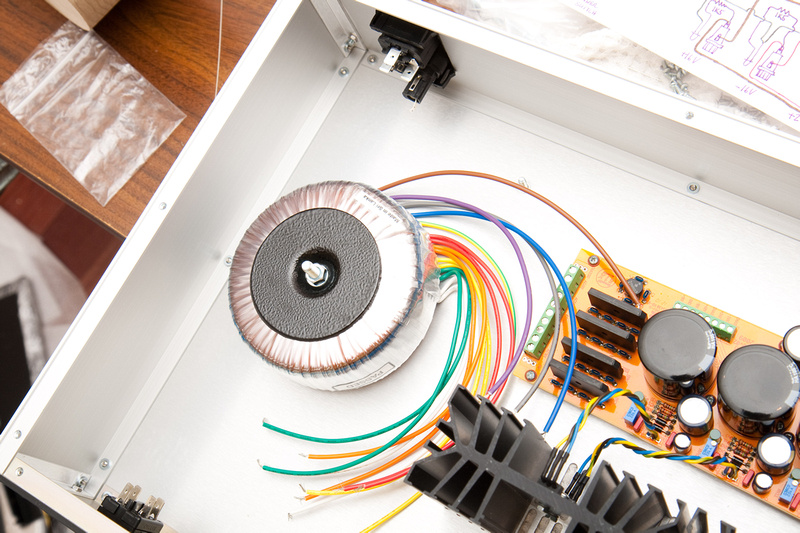
Here's a closeup of the port in question:

if you look left of the 3 resistors and directly above the Trimmer, there is a 2-prong green component with the +16v, -16V, +24V, -24V and +48V silkscreened next to it. Is that where the LEDs were supposed to connect to, in the first design? Chunger's wiring diagram doesn't show the LEDs being connected to those holes on the PCB, so i'm unsure what is supposed to go there, as his pics show that space filled in with something green and cylindrical.
Here's chunger's board:
Here's a closeup of the port in question:


![Soldering Iron Kit, 120W LED Digital Advanced Solder Iron Soldering Gun kit, 110V Welding Tools, Smart Temperature Control [356℉-932℉], Extra 5pcs Tips, Auto Sleep, Temp Calibration, Orange](https://m.media-amazon.com/images/I/51sFKu9SdeL._SL500_.jpg)


