Collins 26C Analysis

GroupDIY Audio Forum

Help Support GroupDIY Audio Forum:

This site may earn a commission from merchant affiliate links, including eBay, Amazon, and others.
Looks like a trusty old ECC82 would also get you there
Yes you are right, it would do the job, but I was sticking to the same type, mu20 ra10k.
The replacement for the 6J7 was the single ended 6SJ7 and that has the same triode characteristics as the 6J5 and half of a 6SN7, the ECC82 comes into that class as well.
best
DaveP
 
Point taken, I need to look at *all* the parameters when looking for subs. I guess in this case Ra is of particular interest since we're driving transformers. ECC82 has mu17, but higher Ra (47k if I read the spec sheet right).

This would be a fun and useable project to recreate! Following with great interest!
Cheers, V!
 
The 6C8G tube is rather special, no-one tried to copy it and it looks like it was only made by RCA and TungSol. Each section has this characteristic:-
mu 36, ra 22.5k, gm 1600. It was introduced in 1937. It contains two independent triodes, albeit that one has the top electrode for its grid. Its heater current is the usual 0.3A whereas its closest cousins are the 6A6 and 6N7 which both draw 0.8A, the characteristics of these tubes are mu 35, ra 11k, gm 3200. My guess is that the internal dimensions are similar but the higher heater current increases emission and this increases the gm and reduces the ra. The 6N7 was initially used as the resistance tube in the Collins 26W, but it was replaced by the 5814A which is a special quality ECC82/12AU7.

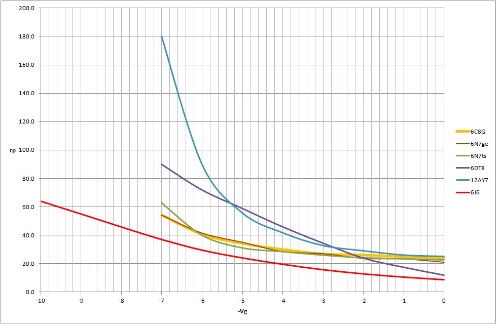
The successor tube to the 6C8G was the 12AY7, but as the chart below shows, it does not have the same characteristic curve:-

I have plotted two examples of 6N7 and they are very close to each other and pretty close to the 6C8G as well. The 6J6, 6DT8 (ECC81) and 12AY7 are not close at all. I have some research to do on other possible replacements and will post that next.
best
DaveP
 
6J7G: I'd stay w/this original tube family, as they are still plentiful, and are great tubes, esp. the metal 6J7 (and using vintage metal top caps for excellent shielding), IIRC european EF37A is also similar. Even Soviet 6J7 copies -- 6Zh7 -- aren't bad and are cheap. If I'm not mistaken, later development lead to 6BR7/6BS7 special quality noval tubes, but those are available in much smaller numbers.

6C8G: Very odd tube, hardly anything like it, 6N7 is much more plentiful and would be a better choice, at least on paper. That said, 6C8G are still somewhat affordable.

The output stage is probably not that critical so the 6K6s (if you don't have them) can be substituted/altered for 6F6 or 6V6 (or 6AQ5 which are also plentiful, but I'd stay w/octals, personally)?
 
6J7G: I'd stay w/this original tube family, as they are still plentiful, and are great tubes
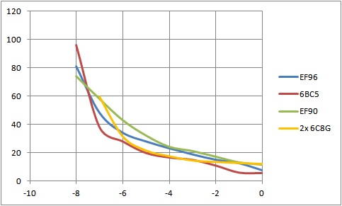
I am exploring other tubes because the original transformers are no longer available. If we use modern transformers with less inductance, then we need a lower output impedance from the tubes to maintain good low frequency response. More on this later.
Some B7G Pentodes have a good triode performance that is reasonably close to a doubled 6C8G:-

The curves I have drawn are a bit wobbly because it is difficult to get the tangent right at such low currents. In fact, where the curves reach zero current, this may not have been recorded so accurately as the main lines. The main criteria for the resistance tube is to present a low resistance at one end (to join the transformers) and a sufficiently high resistance at the other end to isolate the transformers. It goes without saying that there should be a nice smooth transition between the two.
There will be more on B9A tubes to follow.
best
DaveP
 
Last edited:
The B9A tube survey process takes a lot of time, but it is possible to make some progress on the transformer issue.
I have attached the spec sheet for the Hammond 124E interstage as an example.
This quotes a frequency range of 150Hz to 15kHz and a primary inductance of 15.9H which does not look too promising at first glance, but if we inspect the data it looks more hopeful:-
f-3dB = Zsource/2pi x L, so from the data we have 15,000/6.283 x 15.9 = 150Hz, so this checks out with the spec sheet.

If we just sub this TX into the 26C as it is, we will have poor bass response, but if V1 were followed by a cathode follower we would have a response more like this:- 1000/6.283 x 15.9 = 10Hz.
If V1 was substituted for a twin triode, then the first half is the voltage amp and the second half the CF. This could be a 6SN7 or even a 12AU7/ECC82.
Food for thought......
best
DaveP
 

Attachments

  • 124E.pdf
    305.1 KB
A side observation:
The split-load or concertina phase splitter or invertor was developed in Australia in 1936, (Radio Constructor’s Guide, National Magazines Ltd. Wellington NZ (1936), p. 135. Circuit developed by Wireless Weekly magazine (Australia). Bearing in mind the remoteness and speed of communication in those days, it is not surprising that a conventional transformer was used in 1938 to feed the push-pull output stage for the 26C. Nowadays a simple triode could do the same job a lot cheaper.
best
DaveP
 
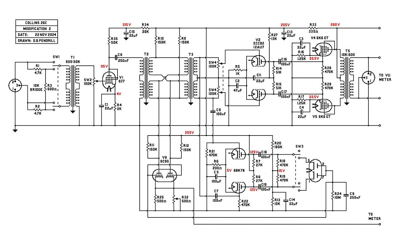
I have re-drawn the original schematic and values to allow me to make a few possible modifications:-

This modification loses an expensive transformer for the substitution of a double triode. I will also cost it with modern components.
Best
DaveP
 
Last edited:
A completely original NOS tube set will cost $122.50 :-
V1 6J7-G $22.50
V2 6J7-G $22.50
V3 6R7-G $15.00
V4 6K6-G $25.00
V5 6K6-G $25.00
V6 6C8-G $12.50
V2 substituted for ECC82 $15.00
But there are other versions of these tubes that would cost less...............
Best
DaveP
 
This set of glass/metal NOS tubes will cost $51.00 :-
V1 6J7 $10.00
V2 6J7 $10.00
V3 6SR7 $3.50
V4 6K6-GT $7.50
V5 6K6-GT $7.50
V6 6C8-G $12.50
V2 substituted for ECC82 $15.00
Best
DaveP
 
It is now possible to work out the gain structure of the 26C. The sales Lit. states that the maximum gain before limiting occurs is 60dB or 1000 times.
This is how that comes about:-
For an input of say 0.02V into the 200 ohm IPT we get 14.5 x 0.02 = 0.29V.
0.29 x 13 from V1 = 3.77V
Losses from the two limiting transformers in series would be approximately 3.77 x 0.9 = 3.393V.
The gain from V2 would give 13 x 3.393 = 44.1V.
The loss from the phase splitter TX would make that 0.95 x 44.1 = 41.9V.

Working backwards from the 60dB gain giving an output of 20V:-
The OPT is 10k:500 so the ratio is 4.47, but its reduction with losses would make that 4.47/0.95 = 4.7.
So 20V on the secondary would need to have 4.7 x 20V on the primary = 94V.
We can now calculate the gain of the output tubes as being 94/41.9 = 2.24. This would be about all we could expect from the 6K6 with the chosen working point.
best
DaveP
 
At this point it is worth considering some alternative tubes:-
It is well known that TV/Audio produced some very useful tubes by combining two tubes in one envelope. We have come across tubes like ECL82/3/5/6 that have been used in audio before but these are now becoming rare and expensive, also they are triode/pentode types.
What I am suggesting are the range of "Dissimilar Triodes". Taking the 6CM7 for example, it has a 6C5/6J7triode wired triode in the same envelope as a very useful output tube, all in a B9A tube. This means that a 26C could be made with two less tubes if space was tight.
Edit> I have attached the table as it did not display properly here.

best
DaveP
 

Attachments

  • Tube Comparison.pdf
    80.6 KB
Last edited:
I have been working on the costing of the original schematic and it's quite expensive in transformers.
Resistors $22
Capacitors $11
Tubes $51
Switches $21
Transformers $713 (Hammond 800A series)
There would also be tube bases and terminals and chassis etc but we already have a total of $818.

I will see if this can be brought down to something more affordable.

Attached transformer list
best
DaveP
 

Attachments

  • Transformer List.pdf
    94.8 KB
The phase-splitter modification I posted on #31 would add $15 for the ECC82 but lose $144 by avoiding T4 making a reduced total of $689,
but there is more that can be done by avoiding the use of T6 as well...............
best
DaveP
 
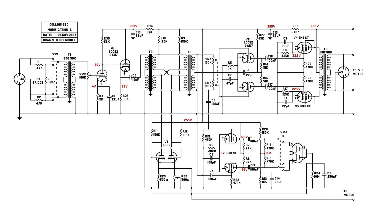
This second modification needs one more tube, but loses the side-chain transformer.:-

The 6R7 was able to give a source resistance to the timing circuit of 8k, because its rp was reduced by the transformer. In order to keep the same timing, the drive tube is changed to a 6BK7B with a working point of 8k. The new tube is a double diode like a 6H6 or 6AL5, or even a pair of 1N4007.
This modification takes the transformer bill down to $527 and because T3 is wired in push-pull there is no need for a phase-splitting stage. I would also expect the push-pull to cancel some noise as well, maybe -3dB?
best
DaveP
 
Last edited:
This third modification allows a lower inductance transformer to be used, like the Hammond 125E which is 15.9H, and with a 15k source impedance it gives a 150Hz -3dB point. If we sub the 6J7G for a 12AU7 or a 6BK7-B with a cathode follower, we get a much lower source resistance to drive the transformers.:-


With the 12AU7 we get a source resistance of 1250 ohms which gives us a -3dB of 12.5Hz, but with a 6BK7-B we get 450 ohms and 4.5Hz.
I have calculated the components for the 12AU7, but the 6BK7-B would be similar as it is mainly the gm which is higher.
Using the 125E transformers saves $181 bring the total project cost down to about $460 for components.
best
DaveP
 
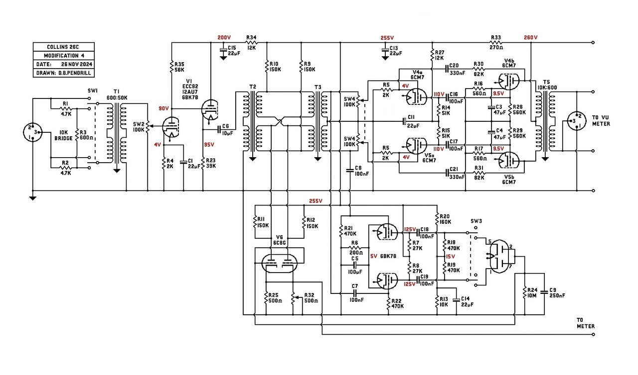
Still trying to make the project more affordable, this is modification 4.

have removed V2 12AU7 and the 6K6's and substituted them with just 2x 6CM7 double triodes. Each one has a 12AU7 section and a heavy duty output triode. So these two double triodes do the work of the three former tubes.
To keep the gain the same we get a little bonus as follows.........
The original output stage gain was 13 x 2.24 = 29.12.
The new arrangement gives more gain, 9.39 x 9.25 = 86.85
So we can equalize the gain by using some for NFB. (the gain of the first tube is only 9.39 because there is no by-pass cap)
86.85/29.12 = 2.98 which is 9.5dB of NFB. This has the double benefit of reducing noise and lowering the output impedance.
I have calculated that this output stage is capable of providing up to 2W which is more than enough.
best
DaveP
 
Last edited:

Latest posts

Back
Top