Console VU meter causing THD problem

GroupDIY Audio Forum

Help Support GroupDIY Audio Forum:

This site may earn a commission from merchant affiliate links, including eBay, Amazon, and others.
living sounds said:
Kingston said:
The fix is completely separate RC's (damping stages) for the meter driver opamps. 20ohm and 22-47uF are probably fine. You can dump their dirt to the same garbage drain you are already using for the rest of the system.

So a 20ohm resistor each in series with the +/- supply lines for the TL074?

yes, with reasonably big caps locally at the opamp. Involves cutting the traces that are already going to the meter opamp, and replacing them with the resistors. This is often done at current sucking sections, like headphone amps to isolate and clean up the rails at the same time. 10ohm/220uF in my mixer for example.
 
JohnRoberts said:
If you unplug the meter does the distortion still increase when meter is selected?

JR

No, it doesn't. So the rectifier in the meter has to be blamed, right? Or could adding local dampening resistors to the op amp's supplies as Kingston suggested help?
 
Because of the rectifier, the meter looks like a non-linear load.

This nonlinear load can generate distortion at the drive point if there is significant source impedance.

This nonlinear load, when driven by a linear voltage will also sink a nonlinear current into the ground.

So the nonlinear load can express in several places, 1- at the driver interface , 2- at the ground, 3- in the PS rails.

#3 The PS rails should not be a major suspect.

#1 At the driver output, this is mainly causing distortion at the send to the meter. In the schemo it looked like the meter has it's own buffer

#2.. I'm kind of guessing, but again looking at the scheme the meter connector ground looks like a straight shot connection to all your other master section grounds.

What happens if you run a different wire between the meters and PS ground?

But still guessing, why is there +V and -V on the meter connector? Sounds like there is active circuitry in the meter section?

Warning- I do not have a very clear picture of the signal flow from that Schemo...

JR
 
living sounds said:
I've decoupled everything with electrolytic caps, which - according to the discussion in the other thread - provided sufficient inherent resistance to provide damping.

But in other places you mention you also have ceramic bypass caps. And what kind of electrolytics exactly? ricardo's "damping within electrolytic" trick doesn't work with modern electrolytics - which can just about all be considered low-ESR. You need to manually add the series resistance. Either in series with rails (easier if you already have the local ceramics and electrolytics soldered in everywhere) creating the RC stages I've been explaining, or in series with the electrolytic itself (no experience with this trick).

Your situation sounds a lot like you have a jumble of somewhat random capacitance spread around the board with no plan. The damping part was the single most important thing to lower THD+N in my project for example. Seems to me you did none of that? Those separate dirty grounds only remove noise, but do basically nothing to THD, which is what you are probably seeing as well. You still have a lot of interaction of opamps through rails with no control over it and this is a major source of high frequency THD and very likely causes oscillations.

If you really want to clean up those strips, you need local damping everywhere - cut the opamp interactions completely. This involves a lot of trace cutting and local 4r7 - 20 ohm resistors with their respective caps.

It suddenly seems like a lot of work doesn't it?
 
JohnRoberts said:
But still guessing, why is there +V and -V on the meter connector? Sounds like there is active circuitry in the meter section?

I was wondering about that too. 10 ohm resistance at the rails there too (but no elco). Where do they go?
 
Thanks again!

The complete schmatics are here:

http://www.google.com/url?sa=t&rct=j&q=&esrc=s&source=web&cd=1&cad=rja&ved=0CCUQFjAA&url=http%3A%2F%2Fwww.gearslutz.com%2Fboard%2Fattachments%2Fgeekslutz-forum%2F53786d1206498037-soundcraft-200b-troubleshooting-group-headphones-schematic-200b_schems_only.pdf&ei=LxFyUPPiF4nl4QSz-YDQBQ&usg=AFQjCNGkezTZnCfKa9eMS5LPGc19ANv8TA

The +/- connections at the meter are for its illumination. I've added some more resistance at the meters to drop the voltage so the LED's I put in instead of the bulbs work.

I'll try to isolate the meter driver op amp ground from the rest and connect it to star ground instead.
 
Kingston said:
But in other places you mention you also have ceramic bypass caps. And what kind of electrolytics exactly? ricardo's "damping within electrolytic" trick doesn't work with modern electrolytics - which can just about all be considered low-ESR. You need to manually add the series resistance. Either in series with rails (easier if you already have the local ceramics and electrolytics soldered in everywhere) creating the RC stages I've been explaining, or in series with the electrolytic itself (no experience with this trick).

Your situation sounds a lot like you have a jumble of somewhat random capacitance spread around the board with no plan. The damping part was the single most important thing to lower THD+N in my project for example. Seems to me you did none of that? Those separate dirty grounds only remove noise, but do basically nothing to THD, which is what you are probably seeing as well. You still have a lot of interaction of opamps through rails with no control over it and this is a major source of high frequency THD and very likely causes oscillations.

If you really want to clean up those strips, you need local damping everywhere - cut the opamp interactions completely. This involves a lot of trace cutting and local 4r7 - 20 ohm resistors with their respective caps.

It suddenly seems like a lot of work doesn't it?

I used the cheapest electrolytics I could get, but they're probably lower ESR than really old ones. Additionally to the three electrolytics I have a ceramic cap rail-to-rail on each op amp.

Believe me, this already was a lot of work. ;-) And it sounds great and the THD measured is at the limit of my converters (Lynx Aurora). But I'm not using high speed op amps now, the TLE2072 for example still sounded worse, so yes, the environment isn't as good as it is (accepting the premise that these op amps are transparent if implemented properly).
Hum or noise isn't better though. But I'm also still using the crappy stock PSU (upgraded or not), and the new one is something else entirely.

But I'll look into the series resistor thing, too. Obviously a resistor in parallel with the electrolytic cap would be easier to do...
 
living sounds said:
Thanks again!

The complete schmatics are here:

http://www.google.com/url?sa=t&rct=j&q=&esrc=s&source=web&cd=1&cad=rja&ved=0CCUQFjAA&url=http%3A%2F%2Fwww.gearslutz.com%2Fboard%2Fattachments%2Fgeekslutz-forum%2F53786d1206498037-soundcraft-200b-troubleshooting-group-headphones-schematic-200b_schems_only.pdf&ei=LxFyUPPiF4nl4QSz-YDQBQ&usg=AFQjCNGkezTZnCfKa9eMS5LPGc19ANv8TA

The +/- connections at the meter are for its illumination. I've added some more resistance at the meters to drop the voltage so the LED's I put in instead of the bulbs work.

I'll try to isolate the meter driver op amp ground from the rest and connect it to star ground instead.
No.. I'm talking about the ground coming back from the actual meter.. that current from the meter may be the source of nasty nasty.

JR

PS: I will try to look at more of the schemo another time.. not tonight.

 
JohnRoberts said:
No.. I'm talking about the ground coming back from the actual meter.. that current from the meter may be the source of nasty nasty.

JR

PS: I will try to look at more of the schemo another time.. not tonight.

Makes sense, and is easy to do. I'll try it tomorrow, thanks!
 
JohnRoberts said:
No.. I'm talking about the ground coming back from the actual meter.. that current from the meter may be the source of nasty nasty.

You were spot on, John! With the meter ground connected to chassis ground all I get is slightly elevated 2nd harmonics for a 1k testtone from turning on the meter, none of that nasty large higher harmonics increase.

It's probably good enough for serious work now, but since I'm at it: The meter driver's noninverting inputs are still connected to audio ground, would putting those on the dirt ground (= a seperate ground connection to the star point) get rid of that last bit of distortion?

Thanks!
 
Drivers and meter are now both grounded to the dirt ground, but this didn't further lower THD when the meter is on (2nd harmonic is about 6db elevated vs meter off).
 
living sounds said:
JohnRoberts said:
No.. I'm talking about the ground coming back from the actual meter.. that current from the meter may be the source of nasty nasty.

You were spot on, John! With the meter ground connected to chassis ground all I get is slightly elevated 2nd harmonics for a 1k testtone from turning on the meter, none of that nasty large higher harmonics increase.

It's probably good enough for serious work now, but since I'm at it: The meter driver's noninverting inputs are still connected to audio ground, would putting those on the dirt ground (= a seperate ground connection to the star point) get rid of that last bit of distortion?

Thanks!
The opamp + inputs are high impedance so not a source of dirt.

It would take more brain cells than I have awake right now to give optimization advice about grounds.

It appears the nonlinear current from the meter was corrupting a clean reference ground.  Low order harmonic could be coming from PS currents, since + supply and - supply each get half the current draw, but don't kill yourself, looks like good progress already.

JR
 
Thanks, I'll tackle the PSU next then. Researching about super regulators I finally found this nice DIY project (I'll report back once it's finished):

http://www.amb.org/audio/sigma22/

Supposed to be about as good as it gets and will perform well under load with adequate cooling.


BTW, this guy has one of the best discrete regulators (and some interesting comparisons on his website, confirmed by other people's measurements it seems):

http://www.belleson.com/

And there's a design by a John Roberts mentioned in his patent application as prior art:

http://patentscope.wipo.int/search/en/detail.jsf?docId=WO2010151417&recNum=1&docAn=US2010037556&queryString=FP:%2528wo/2010151417%2529&maxRec=1
 
living sounds said:
And there's a design by a John Roberts mentioned in his patent application as prior art:

http://patentscope.wipo.int/search/en/detail.jsf?docId=WO2010151417&recNum=1&docAn=US2010037556&queryString=FP:%2528wo/2010151417%2529&maxRec=1
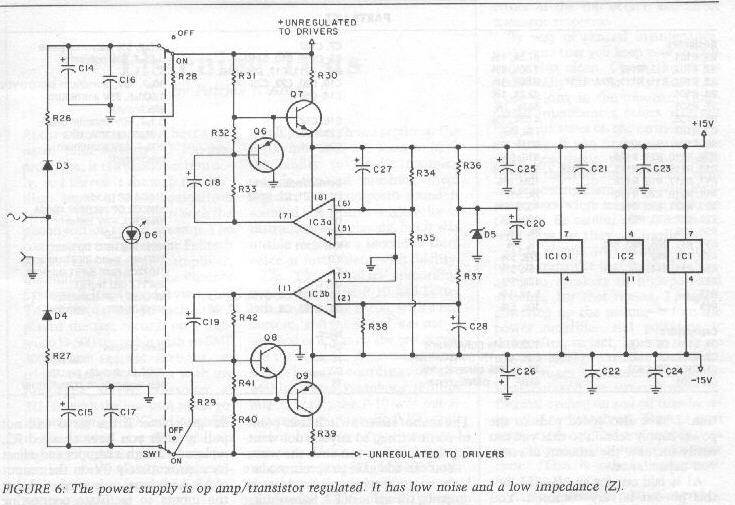
Yup, that was my exercise in over-engineering a regulated PS. For audio circuitry it's kind of a raise the bridge-lower the water relationship. i.e. either make the regulator uber-clean, or design the circuitry to ignore dirt in the PS. Good design is a proper balance of both. Note: the clever thing about that PS design that the guy was referencing, was that I powered my regulator, from it's own regulated rail so PS rejection of the regulator itself would be much improved.

I have never felt a real need to throw so much resource (cost) at PS regulation. The regulator referenced in that application, was in a phono preamp that was over done in several ways. Another PS trick that I published back in the day, was shunting a cheap 3 terminal regulator with a decent sized electrolytic cap. The real impedance curve of the electrolytic cap, flattened out the rising output impedance of the 3 terminal regulator (due to 741 era technology inside).  Of course this technique would have to be reviewed in light of modern electrolytic improved HF characteristics wrt stability.

JR

P100_PS.jpg


Note: for general purpose use, current limiting could be added by sensing across the collector resistors with a b-e junction. I didn't add current limiting for my well defined modest current application.
 
JohnRoberts said:
Yup, that was my exercise in over-engineering a regulated PS.

Thought so.  ;D

JohnRoberts said:
Another PS trick that I published back in the day, was shunting a cheap 3 terminal regulator with a decent sized electrolytic cap. The real impedance curve of the electrolytic cap, flattened out the rising output impedance of the 3 terminal regulator (due to 741 era technology inside).  Of course this technique would have to be reviewed in light of modern electrolytic improved HF characteristics wrt stability.

While researching I also found this trick and put it on my list to try in several projects:

http://www.pinkfishmedia.net/forum/showthread.php?t=23208

7905vbeschematic.png


It seems digital circuits is where the improved PSU performance really matters.
 
living sounds said:
BTW, this guy has one of the best discrete regulators (and some interesting comparisons on his website, confirmed by other people's measurements it seems):

http://www.belleson.com/

Always be wary of the slippery salesman who will assault you with data. The most striking piece of data that puts just about everything there under suspicion is the price. $54.50 is ridiculous!! Especially since he goes on to rave on the simplicity of this design.

It's like the marketing always says: "clinically tested under laboratory conditions"

well, what was the conclusion then? Causes cancer or not?
 
Kingston said:
Always be wary of the slippery salesman who will assault you with data. The most striking piece of data that puts just about everything there under suspicion is the price. $54.50 is ridiculous!! Especially since he goes on to rave on the simplicity of this design.

It's like the marketing always says: "clinically tested under laboratory conditions"

well, what was the conclusion then? Causes cancer or not?

People in forums have apparently tested it with quality analyzers and confirmed the measurements. But yes, at the price point I decided to just build a new PSU.
 
Ironically perhaps a high performance power supply will help a weak design more than a robust one. A design with lousy hum rejection will benefit from less PS hum.

I tend to focus on making the designs right, but sometimes the PS is the easier option for inhabitants of DIY land.

JR
 
living sounds said:
People in forums have apparently tested it with quality analyzers and confirmed the measurements. But yes, at the price point I decided to just build a new PSU.

I had to go and check that site in detail. I don't know what forum and tests you are talking about but based on that marketing I'd say it's head-fi. I sincerely hope you understand what that means.

Further more, his tests especially against Jung regulator is completely rigged. First of all, his regulator result is actually inferior, and secondly, he removed the pre-regulator of the Jung design! wtf, why? That's the ingenious strong point of the whole thing!

It's like some overpriced family Skoda against a Ferrari with no steering wheel.

His criticism is also on the level of "Jung regulator has a lot of caps"...
 

Latest posts

Back
Top