Converting Yamaha PM2000 to API (kind of) using CAPI 2S-LA cards.

GroupDIY Audio Forum

Help Support GroupDIY Audio Forum:

This site may earn a commission from merchant affiliate links, including eBay, Amazon, and others.

JW

Well-known member
Joined
Jun 8, 2005
Messages
1,113
Location
Portland USA
I've seen the 312 and 325 cards in the technical docs. I'm wondering though, concerning the consoles these were used in. Was it XLR>pad/switching network>2622>312 card, or is the first instance where you can control volume the negative feedback control, like in a standard 312 mic pre?

I'm trying to understand how a line level signal would typically come into the console.

Is there a switching network that bypasses the 2622 to instead go straight to the opamp in a 325 card?

 
Okay,
Answering my own questions here. It looks like the line input is switched to go directly to the opamp, and not through the 2622. Here's a block diagram I found: https://1d91d2c1-a-62cb3a1a-s-sites.googlegroups.com/site/soundtwister/api-custom-mixing-desk-1604-1608-from-the-70/api1604_program_block.jpg?attachauth=ANoY7cohUls200KLzx25FRIY8XLII-eC2I4SpuwdezyTDfGYmYt5KuvigFyHKgvqOAVuskdGXbqQ2UjoZJXx5rMwFMbJU_769CoybAvJwZ6bewxO4Y6wPXmIobq3pEd41wG2rwdHAJgFugdOQrHaHpAdLCEvlh5n_1XVaBIVZV8iZyvFRNAQkPgN0KLgUOl-dI6mQCrWOovYhYw5WKzdPQ0JkKyVgaqZl3-bAKNE4DCq6YUJOISZjjWAJ0izc02n7m1juBb5L3hzI70Bh1tXrEnvZjiyPZT4AykvQFwMmw1PNQYBkOHNPsw%3D&attredirects=0

So, the "BTA Network" prior to the first opamp is a multistage resistive network switch?

So, if we're dealing with a line input, is the negative feedback volume control of the first opamp fixed, or is it another pot?  Or is it just available in mic pre mode? Both 312 and 325 schematics show where this volume control would go, but the 325 I'm guessing has fixed gain in various stages of the console, right?

Background: I have a Yamaha Pm2000 console for which I'd like to experiment with a channel or two, copying the API line amp. (Not the eq for the moment. . . . just two stage line amp. One for the input and one to boost after the fader)
 
Look on the second page of the API subject in the Tech Docs section where I posted the schematic of the 528
input module and copy that, omitting all the bits you don't need!
 
Thanks very much. Unfortunately it's hard to make out values on the input section. Correct me if I'm wrong but it looks like the mic/line switch is a 4 pole switch that also switches between different feedback (gain)  pots. Is the one for the line section a 1K pot?
 
Yes 4 pole switch. The 1k is a trimmer for CMRR.
PM me an email address and I’ll send you a clearer pic of that section.
 
Yes 4 pole switch. The 1k is a trimmer for CMRR.

Yep!

I recall PRR suggesting that since 0.1% resistors are not so expensive anymore, it makes trim a bit redundant.

My old reverse, gosh going on a decade ago!
https://groupdiy.com/index.php?topic=39204.msg483972#msg483972
 
Boji, on your redrawn schematic  from a 536, you show the phantom filter resistor as 100 Ohms. But in the 548 channel, this resistor is actually 10k!
This can seriously limit the voltage available certain mics, and hence headroom.
TLM150’s for example.
I think this may be one of the factors that gives the API sound on the 2488 desk.
 
Walrus said:
But in the 548 channel, this resistor is actually 10k!
This can seriously limit the voltage available certain mics, and hence headroom.
TLM150’s for example.
I can testify to that. In 1978, I designed a phantom powered DI, while I was at Barclay studios. It used TL071's, but I found that, although it worked fine on the Neve, it just wouldn't with the API. That's how I found about the 10k. I never knew if it was an assembly mistake or a design error...
I ended up using LM308's...

I think this may be one of the factors that gives the API sound on the 2488 desk.
I don't know. The desk was essentially used with dynamic (RE16 and RE20) or non-phantom mics (U47 and U67).
 
You show the phantom filter resistor as 100 Ohms. But in the 548 channel, this resistor is actually 10k!

It's been so long, not sure if the lower value was suggested:

lNXK2Py.jpg


500 series slots took over mic section of the 536 for my project. Still, good comparative catch!

Aside: Kept the line-in circuit true to schematic despite the removal of high Z because....no circuit analysis chops, and thought the switching solution API chose might've contributed to the sound.
 
Values higher than 6.8K for phantom power feeds are not entirely unknown. I have seen some old Neve schematics where 18K was used.

Cheers

Ian
 
Hi,

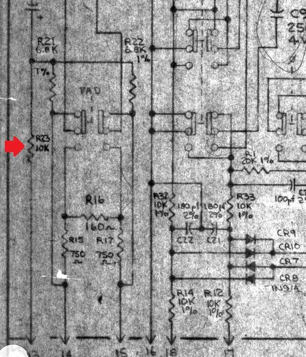
I bought one of Capi's two stage line amp cards and drew out the schematic for the first stage (attached), which appears to be the same as Boji's schematic redraw. Almost anyway, but not quite.
Questions are

1. Should I be building that input stage like Boji's schematic? (see here https://groupdiy.com/index.php?topic=39204.0)  or just stick with how Capi does it? The difference is the extra set of 10K resistors, the diode network, and the two 180 (is that pF or nF?) caps to ground.

2. At the output of the first stage I can wire my fader, but is 10K okay instead of 1K here? Will that be too much source impedance for the second stage?

3. How necessary is a 1:2 interstage transformer if I'm not feeding direct outs or an eq circuit at this stage (after the fader) Can I just make it up by adjusting the second stage's feedback?


Attachments

  • DSCN5141.jpg
    DSCN5141.jpg
    104.1 KB
Can't help but wonder, but can I insert my current Yamaha eq circuit? Consider the output of the first API stage as going into that 6.8K resistor on the top left.  I believe the Yamaha circuit forces the signal thorough IC 5 and 6 regardless of whether the eq is switched in or not? I'm having a hard time telling. If I could bypass this stage with the normal eq on/off switch, or switch it in if desired, that would be ideal for the short term.  This stage feeds the fader, like API. But I have a 10K fader. That would feed the second DOA, which would feed by bus and aux network. 
So, API line in 1ststageDOA>Yammyeq switchable (I don't like it much but it's better than nothing)>Fader(10K)>2ndstage API DOA>back into where Yamaha's DOA outputs into all the auxes and bus routing.

It's inserting the eq that I have questions about. Is it necessary to pass through that first IC? (IC5)
 

Attachments

  • Screen Shot 2021-02-19 at 12.04.33 PM.png
    Screen Shot 2021-02-19 at 12.04.33 PM.png
    206.4 KB
What gain staging do you need? The extra 10k make a -6dB receiver, which is then recovered by a 1:2 transformer. A 0dB receiver and no transformer would be equivalent gain wise.  The diodes and capacitors provide overload and RF protection.  Not strictly required,  but a good idea for an unknown environment.  A 10k fader is fine (preferred imo),  provided it is feeding a decent load.

Part of what you have drawn out is remnants of an input to accommodate mic and line signals.  Good if you want to be authentic to the original design. But also unnecessary if you simply want a good performing line input receiver.
 
Should I be building that input stage like Boji's schematic

1) I'd go with Jeff's if you want to capture some of the sound of the console in 500 format without diy-ing a pcb.
Also I think VP28 has pin headers for tapping off A1, but not bypassing?? (I don't recall, bypass for insert send / returns might be offered in his 'missing link' / 'audio bacon' models)
If you're building a diy console and want to do it like they did back in the day where 1st stage (A1) drives Aux sends, taps 1st tx for direct outs, as well allows 500 series insert returns to drive fader before A2 / Tx#2 makeup gain, the 536 might offer a little more freedom during design.

2) 10k is fine, and possibly preferred if A1 is loaded with mults.    edit: jinx 12ax!  8)

3) 1st stage TX out's are good for playing with outboard inserts (galvanic iso / cmrr) which you want if you ever got eq's or minimal paths to daw on your mind.

Part of what you have drawn out is remnants of an input to accommodate mic and line signals.  Good if you want to be authentic to the original design. But also unnecessary if you simply want a good performing line input receiver.

+1
 
Thanks very much for the answers you guys. I only bought one of those CAPI cards just because I wanted to picture it and hadn't found Boji's schematic yet. I have a couple bad channels on my console (Yamaha PM2000) that I haven't bothered to trace down the problem yet. My idea was maybe I could build API console channels (line amps only for mixing returns) out of these PM2K strips and see if I can use some things like the eq, and all the aux and buss sends, and panning and switching, as well as the DOA's. Really it's almost all there. I might have to commit to mangling the pcb a bit though. But just thought I'd clear up, this isn't a 500 series project, it's a Yamaha PM2000 mixer modification (PM2K often referred to as API clonish, but it's not. Signal runs through a lot of IC's on the way to the sum bus) But my desire is to plug a modded channel right into the console, and hopefully have it function in place of the PM2000 circuit as it were, but use all the same conveniences. 

So, if I am to have the Yamaha's switchable eq circuit on a channel, I might want to look for an interstage transformer? Incidentally the PM2000 Mic in transformer is a 1:2, but I'm guessing it could very well clip at this level.

Anyway, on the other hand, if I don't have an interstage transformer, it sounds like that -6dB is already made up for me by the lack of those first 10K series resistors. So, fine to omit the transformer if I'm only loading the first stage with the fader and then right into the second stage? (edit, nope it also drives the auxes like you said Boji. when the switch is in "pre" eq position. Duh) Hmmmm. I see. Might need the insterstage.


Just wanted to say I successfully installed Capi's 2 stage line amp in my Yamaha PM2000 input channel.

So here's what I have right now:

Strictly line ins (I have enough preamps) The balanced input goes to the inputs of Pier Paulo Abbate's APP992 opamp (via the CMRR network) On the output of the first stage I've wired in Yamaha's existing inserts (just unbalanced switching jack inserts, no transformer) which return to the on/off switch like in Boji's/API schematic. Then to the fader, then on to the second stage where I'm using Yamaha's discrete 80100 DOA. The output of this successfully feeds my 8 buses (spelled it right Abbey!) and 6 auxes.

Using the console's +/-24V rails, I can't use 2520's, nor do I want to, with Yamaha supplying a lot of DOA's for me already.

Anyway, the sound is . .. . fabulous.

Now I need to figure out if I can insert Yamaha's eq stage with no insterstage transformer, but very short cable run, and the elimination of the first pair of 10K resistors on the input. So I guess I'll be hitting the first opamp harder, but then again the APP992 has headroom for days.

Okay, one question for now though. On the CAPI site, Jeff mentions the trimmer for the second stage opamp as a place that one could take an extra gain control out to the front panel (rather that setting the trimmer on the card, or a fixed value, like 20K in API's case) This is the usual feedback gain adjustment spot. 

The BOM for the CAPI 2SLA lists this trimmer as 10K-25K, so I tried a 10K log pot but it didn't do anything. I'm guessing I would need a rev log 20-25K pot like in a 312? But that's a mic amp. But shouldn't the gain pot match the feedback resistor value?

And this brings up the question of whether is makes sense to have this extra gain control in the second stage? So, after the fader. Why not have it in the first stage, so you could possibly bring down a 'juiced up' first stage with the fader? And have the second stage fixed gain.

From the Boji schematic though, it looks like the API line mode has both opamps fixed gain with the fader as the only vol. control. Fine I'm sure, but I do have a hole in my channel strip that needs filling as I removed the Yamaha input switch assembly. So a simple gain pot would do that nicely, and allow some more flexibility (?)
 
Oh yeah,

Would it be okay to include the diodes and 100pF caps on the inputs if I'm not using that first pair of 10K resistors?
 
insert Yamaha's eq stage with no interstage transformer

When EQ is not in circuit, A1's tx boosts gain which the fader enjoys, as well is meant to drive aux pots, and back in the day, a passive HPF. But that tx seems most important for isolation, especially if there's an insert that gets put there.

For example, when setting up unbalanced vu's taken directly off A1's output, I accidentally flipped polarity on a few buffers which sent output directly to ground. This burnt-up a few opa's. Consider that had I taken the VU after tx that would not have happened.

make sense to have this extra gain control in the second stage?
If your fader comes later in the chain, perhaps so. If not, you'd of course want a fixed gain that wherever set, the yammy EQ doesn't get overloaded early on material.

Would it be okay to include the diodes and 100pF caps on the inputs if I'm not using that first pair of 10K resistors?

Diodes are for input protection, and should definitely be kept. Caps filter out RF and are somewhat optional.

To your earlier post, someone correct me if I'm wrong, but it looks like IC 5 is part of the eq as the filters loop back to pin7 and IC6 is your make-up gain. It might be best if you mock-up and share a block diagram / composite schematic that cleanly shows exactly where you plan to add the new gear to the desk.
 
Thanks so much Boji for the answers. And your redraw of the input channel schematic has been a HUGE help already. I'm working to put together a better visual of what I'm doing but don't have it together yet.

In the mean time, I wonder if I could specifically ask about the eq switch on my PM2000 eq circuit. (pic of schematic above)

One of the things I would like to understand is why Yamaha chose to have a multi pole switch to switch in all four bands of eq (or ground them in off position), yet still force signal through IC5 and 6.

Wouldn't it have been more prudent, and (I guess why shouldn't I?) hard wire all bands of eq to "on" and then use the existing eq switch to simply switch between the beginning of the eq circuit or fully bypass the eq circuit, including IC5 and IC6. (This seems like it would work ???) and a cleaner signal path when not engaged.
 
Yamaha chose to have a multi pole switch to switch in all four bands of eq. Wouldn't it have been more prudent, and (I guess why shouldn't I?) hard wire all bands of eq to "on" and then use the existing eq switch to simply switch between the beginning of the eq circuit or fully bypass the eq circuit,

Ought to leave this one to my betters, but while eq is disengaged, wipers of pots are floating, correct? This means those paralleled pots act simply as 50k resistors. Signal will avoid those resistances and instead travel around the loop of copper. However when eq is engaged, each gyrator will inject some noise.

I imagine this decision came down to cost, as switching out unused frequencies would mean more components x however many number of channels, as well as possible switching noise from swapping gain blocks.

What comes after IC6? Probably best to answer that with the redraw.
 
Back
Top