livingnote
Well-known member
As if the poor GSSL board hasn't had enough abuse already...
Tough Chicken. Surgery time!

(I wouldn't trust these guys either") That's me on the left)
That's me on the left)
Here is the battle plan:
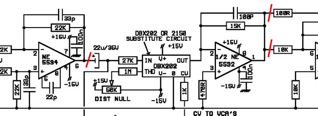
After a bit of thought, I decided it would be best to get in there right before the VCA
input cap, and to go out after the first opamp in the output section.
The idea is to tap off the input, and "break in" to the output. Now there were
some differences on the rev9 board from the rev7 schemo, so we'll be lifting
caps on the output in place of the 100R.
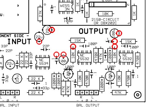
These are the legs we have to lift. It'll be the + side of the input caps, and the
output caps as well as the 10K resistor that goes to the inverting opamp.
In practise, this looks like this:
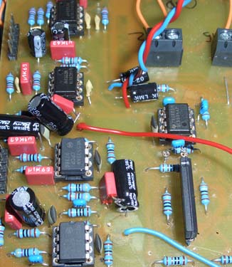
Note that I screwed up a little here, I forgot to lift the output 10K's. Also, I didn't solder
the wire to the input caps' legs, which I corrected (it was 4AM) by soldering a separate wire to the
Cap leg itself and then twisting them together :
Now for the actual connections (blue is left, red is right):
1. On the input caps, solder the lifted leg to the wire and to the hole where it came
from, retaining the original continuity. Alternatively, you can just solder in a wire on the
bottom of the PCB. All we want to do is sniff the signal, while keeping the artery to the VCA intact.
2. Solder the output caps' freed legs as well as the freed 10K leg all together and attach
a separate wire to them.
Now we have our signal tapping point as well as our little "window" on the output to
break into.
Before we proceed, it is a good idea to twist together the output wires respectively
and see if the compressor still works as before. That way, we'll know if we screwed
up here and it will save a lot of headache.
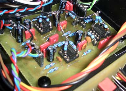
Now for the actual implant:
It's a good idea to power up the CnB board by itself first before you stick it into your
SSL. That way, if you have anything backwards, you'll just screw up a little part of
things.
Additionally, find a good spot for the CnB board well away from the tranny to make
sure it does not pick up hum. Being unbalanced, it's quite the antenna and so special care
must be taken to ensure it stays quiet. (Yah, screwed that one up myself).
On the Crush board, we have LD and RD (Left Dry and Right Dry), these guys get hooked
up to the wires on the input caps.
Next, we have LW and RW on the CnB input, these go where the wire comes out of the
PCB at the output.
Now for the CnB output: Hook this up to the soldered-together-caps-n-resistor legs.
Then, carefully bring your patient back from his anesthesia and if all went well, you have
yourself a blend control.
Side Note: If you want to adapt the opamps' positive terminals to the same R value as
on the SSL itself, well, the Rev2 CnB sticks these straight to ground (which is too bad,
a change I will make in Rev3) and so you have to mod the chip itself.
Carefully bend up legs 3 and 5, and to each of these, solder a 22K resistor to the two input
opamps' legs each, and for the output one, grab two 470R ones.
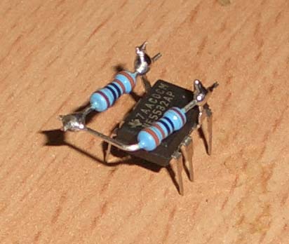
Solder the R's other ends together, and hook that point to ground somewhere.
I can't be sure this really makes a difference, because theoretically opamps have infinite input impedance, but to me it feels as though the construction sounds more "open" with the resistors attached. And then I feel it doesn't again. And then I feel it does.
If anyone has thoughts on this, of course I'd be happy for your input.
This has been an incredible learning experience for me, dotted with a lot of nightmares
when things just wouldn't work. But heck, in the end I built me a working crossfader, and I would like to thank Keef for his original posting that got this all started, as well as Jakob for the SSL that is oh so fun and addictive to tinker with.
Rock on, guys And thank you. Some things you just don't learn in school.
Tough Chicken. Surgery time!
(I wouldn't trust these guys either
That's me on the left)Here is the battle plan:
After a bit of thought, I decided it would be best to get in there right before the VCA
input cap, and to go out after the first opamp in the output section.
The idea is to tap off the input, and "break in" to the output. Now there were
some differences on the rev9 board from the rev7 schemo, so we'll be lifting
caps on the output in place of the 100R.
These are the legs we have to lift. It'll be the + side of the input caps, and the
output caps as well as the 10K resistor that goes to the inverting opamp.
In practise, this looks like this:
Note that I screwed up a little here, I forgot to lift the output 10K's. Also, I didn't solder
the wire to the input caps' legs, which I corrected (it was 4AM) by soldering a separate wire to the
Cap leg itself and then twisting them together :
Now for the actual connections (blue is left, red is right):
1. On the input caps, solder the lifted leg to the wire and to the hole where it came
from, retaining the original continuity. Alternatively, you can just solder in a wire on the
bottom of the PCB. All we want to do is sniff the signal, while keeping the artery to the VCA intact.
2. Solder the output caps' freed legs as well as the freed 10K leg all together and attach
a separate wire to them.
Now we have our signal tapping point as well as our little "window" on the output to
break into.
Before we proceed, it is a good idea to twist together the output wires respectively
and see if the compressor still works as before. That way, we'll know if we screwed
up here and it will save a lot of headache.
Now for the actual implant:
It's a good idea to power up the CnB board by itself first before you stick it into your
SSL. That way, if you have anything backwards, you'll just screw up a little part of
things.
Additionally, find a good spot for the CnB board well away from the tranny to make
sure it does not pick up hum. Being unbalanced, it's quite the antenna and so special care
must be taken to ensure it stays quiet. (Yah, screwed that one up myself).
On the Crush board, we have LD and RD (Left Dry and Right Dry), these guys get hooked
up to the wires on the input caps.
Next, we have LW and RW on the CnB input, these go where the wire comes out of the
PCB at the output.
Now for the CnB output: Hook this up to the soldered-together-caps-n-resistor legs.
Then, carefully bring your patient back from his anesthesia and if all went well, you have
yourself a blend control.
Side Note: If you want to adapt the opamps' positive terminals to the same R value as
on the SSL itself, well, the Rev2 CnB sticks these straight to ground (which is too bad,
a change I will make in Rev3) and so you have to mod the chip itself.
Carefully bend up legs 3 and 5, and to each of these, solder a 22K resistor to the two input
opamps' legs each, and for the output one, grab two 470R ones.
Solder the R's other ends together, and hook that point to ground somewhere.
I can't be sure this really makes a difference, because theoretically opamps have infinite input impedance, but to me it feels as though the construction sounds more "open" with the resistors attached. And then I feel it doesn't again. And then I feel it does.
If anyone has thoughts on this, of course I'd be happy for your input.
This has been an incredible learning experience for me, dotted with a lot of nightmares
when things just wouldn't work. But heck, in the end I built me a working crossfader, and I would like to thank Keef for his original posting that got this all started, as well as Jakob for the SSL that is oh so fun and addictive to tinker with.
Rock on, guys
And thank you. Some things you just don't learn in school.