D-LA2A Support Thread

GroupDIY Audio Forum

Help Support GroupDIY Audio Forum:

This site may earn a commission from merchant affiliate links, including eBay, Amazon, and others.
for all this questions I would suggest doing a search in the LAB for LA2 and author SSLtech.
you can learn many things reading this posts.

a 1:1 transformer at the input will work fine and reduces some gain.
a PAD at the output works only if you want to have some 50% of THD.
the LA2a has loads of gain, which doesn't mean it has high headroom.
 
[quote author=[silent:arts]a PAD at the output works only if you want to have some 50% of THD.
the LA2a has loads of gain, which doesn't mean it has high headroom.[/quote]

Oh. I have always been under the impression it had a severely oversized headroom. Didn't know it is basically a glorified guitar amp. And of course I now have to hear this distortion in action, so pad it is.

I had also been wondering how people are able to use the 10k/600 "small" edcors as outputs. The low clean gain explains it: you won't saturate the trafo (or the gain stage) at any sensible "modern" gain values.
 
On another note - anybody notice that the compress/limit switch seems to have almost no effect? - In fact I wondered whether I had a solder short somewhere because I could barely perceive the difference.

My thinking is that this may be because the comp/ limit comes at the input stage which might be a bit crude and unsophisticated. Guess it doesn't matter because the LA2A is most often used to add some vibe or mojo during tracking rather than as an exact scientific audio instrument and adding vibe and mojo is certainly what it does magnificantly!
 
I think I found the solution to my problem:
I had the A-10's dual secondaries wired in series.

A quick change of the jumpers on the A-10 and I think I have everything sorted...

just got an oscilloscope so tonight is the real test!
 
deuce42 said:
Actually I had wondered similarly about the input tranformers secondary 10k when the schematic seems to want 50k. Guess it is just a matter of trying it and finding what works best for your ears.

I note that there was a post somewhere else on this board where SSL Tech or someone else seemed to be of the view that the best tranny for LA2A was a 600/15k set up becuase it was easier to dig into signals that were less "hot sounding". It appeared as though there was consensus on this board that numerous permutations had been tried and in the end the 600/15k was the best.

Wish I could find it here.

This post?
http://www.groupdiy.com/index.php?topic=26119.40

I ordered 600:15k and 15k:600 edcors following ssltech´s advice on that topic...hope they work great !
 
Yep that was the post I meant!

You did order the "wsm" rather than "xsm" versions though right????

There has been a lot of slander about the edcors screwing up the top end frequencies in the LA2A circuit (including slander on that thread). I read and read as much as I could about them and some other member (I am good at recounting threads without remembering who said them:) queried whether the high end loss could be due to the XSM version being 2.5 watts. This may mean capacitance loss resulting in the high end being muffled.  Generally people rush out and by the XSM version rather than the 0.5watt WSM versions which are cheaper. Actually the LA2A doesn't need that extra 2 watts and this may as described above even result in frequency loss.

Whilst I talk from such authority on this- based only upon hearsay (or readsay if there is such a word:), - it may or may not be true. Regardless of whether this theory is correct, I used the WSM's 600/10ks in my build. For what its worth I heard no high frequency loss whatsoever.

Even more so, I seem to not have found the time lately, but I was hoping to post samples of both the Edcor WSM's and some BBC custom wound Sowters. I heard barely any difference between the pricey Sowters and the $9.90 Edcor's. The Sowters maybe had a little more bass end but the Edcors were really nice and actually found them even slightly clearer than the Sowters.  Now it is true that these are line Sowters (i.e. 600/600 ohm) and the Ecdors are 1:4's so they are not entirely identical but the ten buck Edcors really satisfy me as much as the Sowters.

Will post soundclips soon I promise and you guys can decide for yourself.

 
I try to post soundclips of my D-AOC (very similar input stage to a La-2a) which uses XSM 10k/10k on the input - and I absolutely love the sound! The top end gets softened like you would image a sweet tapemachine to sound - it's beautiful and not 'dull' in any way. On the paper (measured with rhode&schwartz upv) I have slight dip (-1dB @ 20kHz) before the spectrum rises again, but it sounds nowhere like that. As said, I try to post clips soon... I would highly recommend the 1:1 XSM on the input, it may look wrong theoretically, but it sounds mighty fine, at least I like the character (otherwise just use somehting clinical as a Lundahl and compare the sound to your UAD emulation  ;D)

cheers
christoph
 
stitch-o said:
I think I found the solution to my problem:
I had the A-10's dual secondaries wired in series.

A quick change of the jumpers on the A-10 and I think I have everything sorted...

just got an oscilloscope so tonight is the real test!

jumping 7&8 and 9&10 on the A-10 did the trick!!
Using the jumpers to wire the transformer as a voltage divider, I think I have it down to 12.5k
coming form the input transformers secondaries.
Any which way, it sounds GREAT!

fat and buttery on first quick test passing signal.
A pair of 1958 RCA 12AX7's showed today for
the V3 and I have a pair of 5star 6072s coming for the V1.
Left to do is add some LED IN/Bypass indicators.

Has anyone contemplated a 10 or 20db pad on input?

Cheers and thanks!
 
I was thinking of doing a slightly more optimal PSU solution than the dual 6,3 VAC + 5VDC for heaters and relays/lights, but there are a few things I don't quite get.

First of all, why is the d-la2a original PSU transformer suggestion (as already bought by many people here) with dual VAC heater windings? (2X 6,3 2VAC)

Dual LA2A only needs 3.3VAC for the heaters. Hum prevention with dual windings?


So instead I was thinking of using one of these generic 6.3VDC regulators (by moby) with a single 9V 4A winding for both of the channels. Sure needs a big heat sink but so what. Then steal another 5VDC from there with a few caps and a 7805 for lights and relays.

Anything wrong with that? I can't foresee any hum troubles provided the 6.3VDC is already regulated super-clean, but what else might there be.
 
Kingston said:
First of all, why is the d-la2a original PSU transformer suggestion (as already bought by many people here) with dual VAC heater windings? (2X 6,3 2VAC)
I always round up, and it might change only in an Euro.

Kingston said:
Dual LA2A only needs 3.3VAC for the heaters. Hum prevention with dual windings?
the dual windings are just there since it is a dual LA2A. and since I had to order a custom wound transformer, why not. heater wiring is easier in my opinion. haven't thought about hum etc.

Kingston said:
So instead I was thinking of using one of these generic 6.3VDC regulators (by moby) with a single 9V 4A winding for both of the channels. Sure needs a big heat sink but so what. Then steal another 5VDC from there with a few caps and a 7805 for lights and relays.

Anything wrong with that? I can't foresee any hum troubles provided the 6.3VDC is already regulated super-clean, but what else might there be.
try it, why not ?
can't see any problem.
but let us know in the end :)
 
I'm also ordering a custom transformer (for several projects) so I thought about simplifying things a bit. I would have thought dual heater wiring would be less easy. I guess another man's simple is another man's complicated.  ;)

I'll post experiences here when it's done.
 
It seems clear that all the mojo in this project is in V1 besides obviously the trannies.

I have experimented with a few 12ax7 valves for V1. So far the JJ Electronic's ECC83s (direct equivalent of 12ax7) is doing it for me.
 
[silent:arts],

how did you come up with the 150pF value for the cap in C4? (C104 in your schematic)

In every single LA-2A schematic I've seen to date this is marked as 50-380pF, ie. the Arco 465 trimmer cap.


Also, the C114 (T4 response trim) is probably too important to set into "stone" with the marked 330pF. Arco 465 is traditionally used here as well, and it has a strong effect on the compression response, from "flat" to almost "de-esser" like characteristics. Some have even made it into a switch on the front panel.
 
hello every body,

I tried to make a wiring guide  with all information on this thread and techtalk thread.
i don't know if it's good.

"Pictures erased cause was wrong will posted in next page"

i'm not sure about me don't hesitate to says me if there is some error

Other thing need i stuffed like this pictures ?
Cause some people tell me i need to do and some other idon't need cause i have the REv2.
So i don't see track on this 6volt and i think i need to but i prefer have a confirmation.
???

I'm beginer for sure.

Thank you


IMG_3945.jpg
 
cool, will look for some errors / improvements.

stereokillah said:
Other thing need i stuffed like this pictures ?
Cause some people tell me i need to do and some other idon't need cause i have the REv2.

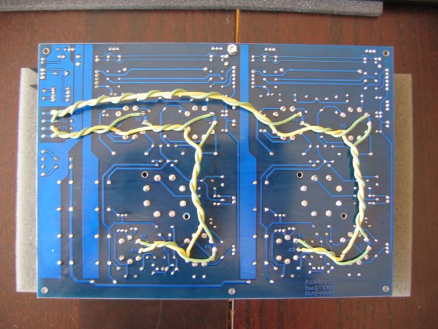
you are meaning the heater wiring at the bottom of the PCB ?
yes, this is the same in rev01 and rev02.
 
few other things after a first look:

the stereo link won't work like drawn. the red wires need to be switched together, the black ones are only for using shielded cables. the shield should only be connected at the molex connectors, not at the switch (if you switch them together you will get a nice ground loop)

for the potentiometers you should use shielded cables too. shield is pin 1 at the molex
 

Latest posts

Back
Top