D-LA2A Support Thread

GroupDIY Audio Forum

Help Support GroupDIY Audio Forum:

This site may earn a commission from merchant affiliate links, including eBay, Amazon, and others.
on pin 1 of the 7805 i have 11.55 and at pl2-2 i have 4.94v. i take my 5v for the LED's from PL2-2. do you think i need to put acurrent limiting resistor in? the LED's are 2 in series and on the VU itself it labels it as 3.6-5.2v 20mA.
 
jonathanmorbin said:
you'll have to excuse me but what value do you recommend i put in? what would my workings out be?
Maybe reread my last reply?
Your 'on pin 1 of the 7805 i have 11.55 and at pl2-2 i have 4.94v' doesn't make sense.
When you measure between pin 1 of the 7805 (multimeters red probe wire) and pl2-2 (black probe wire), multimeter set for reading DC voltage, the multimeter will show a single voltage readout.
pl2-2 is the reference voltage for your +5V rail that has NOTHING to do with your audio reference voltage or ground.
If this readout would be 11.55V, current limiting resistor value would be (11.55V - 5.2V)/0.01A = X ohm. You do the math.
 
jonathanmorbin said:
Thanks for your help, i miss read your first post so got confused. all is ok now and working correctly.
Thumbs up.

It would be helpful if you could measure and post the DC voltage between both meter illumination terminals and the colour of illumination for this type of meter, Mike at hairball is selling.

These Nissei meters come in various illumination colours. Depending on LEDs type and colour or even a colour mix used, this forward voltage differs a lot (red between 1.8-2.1V, blue 3.3-3.6V, ... per LED), hence the 'on the VU itself it labels it as 3.6-5.2v 20mA' for an all avail.colours universal housing.
 
Hi!
I'm looking for informations and wiring guide about D-La2a.
I tried the links on the first page of the thread, but they redirect me to nrg forum, I tried to register me but never received confirmation... so I can't read the documents... Any idea? If someone has information...
Thanx
 
Clicking that link takes you to sonicwarrior's post. The document is attached to his post. You should be able to see it just below it.
 
rob_gould said:
Clicking that link takes you to sonicwarrior's post. The document is attached to his post. You should be able to see it just below it.
Thank you...and shame on me!!!!!
Each time i looked at this post i was logged off... so the link didnt appear...
Log in, and miracle link is here!
 
Hi!
I finished my D-La2a.
It works perfect, calibrated etc... :)
I have two questions:

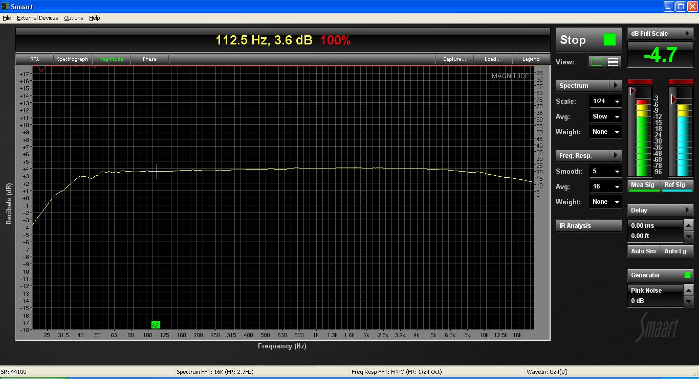
Here is a capture ofmy la2a's  frequency response:
la2a.jpg

There's something like a low cut at 50Hz...  Is it because the tubes or the xformers???
I use Edcor xformer, Mullard 6bq5 and 12ax7(2), Electro Harmonix 12BH7 and Tung sol 12ax7(2).
Edcor WSM frequency response is: 20~20K Hz., <1dBu (datasheet)... I tried to swap the tubes, same result, identical on each channel.
any idea???

Later, I wish to improve this machine... but what first???:
more matched and expensive tubes?
sowter input or output?

thanx for reply
 
IIRC this was discussed already on this post or on the LA2A post.
again, IIRC, you can tweak this with a zobel network.

But for the calculation, your HPF is at 30Hz (the frequency is given by the point where a 3dB attenuation has been achieved) not at 50Hz
 
jplebre said:
IIRC this was discussed already on this post or on the LA2A post.
again, IIRC, you can tweak this with a zobel network.

But for the calculation, your HPF is at 30Hz (the frequency is given by the point where a 3dB attenuation has been achieved) not at 50Hz

Thanx
Ok, I'll do some research about "zobel network"...
 
So...
I found informations about zobel network on the net. I read differents posts on this thread.
But I can't find what I have to do exactly... continue searching
 
http://www.groupdiy.com/index.php?topic=26119.0

I think this was the thread I read when building mine
 
Hi,
I would like to report my findings concerning oscillation. My input transformer is the original Sowter 1:4, Output is Edcor 10K/10K. I did the 25K pot 75K resistor mod for the input gain.

Background: My unit worked fine from the very beginning, except for the annoying 30kHz oscillation with higher gain settings causing meter pegging. I moved the output transformer farer away from the board and the xlr connectors which helped a bit. I consequently used moderate gain setting so that unity gain was almost achieved.

Today I tried various ideas to eleminate oscillation. I realized that the area around V1 and R11 (68K Feedback) is very touchy and that even moving my hand around V1 reduced oscillation a bit. CJ proposed to change the value of R11 in order to reduce negative feedback and gain. I finally put a 14K resistor in parallel to the existing 68K. That helped quite a lot but I still couldn´t crank up the gain to maximum without meter pegging.

Then I had a real "heureka" experience. The shielded wires for the gain reduction pot and gain pot were connected wrong, well not wrong but the shield was conducting signal and a red wire was meant to work as shield. What a silly mistake!!!! I rewired it and now I can set the gain pot to maximum without any oscillation at all. I measured the compressor with RMAA and the specs are more than convincing. With the paralleled negative Feedback resistor THD is 0,382 %. Not that bad. All other values including absolutely flat frequency response are excellent. I´m more than happy now with my Dual LA2a!!

People having these problems as well: CHECK YOUR WIRING (verify that shield is connected to ground!!!) and REDUCE FEEDBACK RESISTOR.


regards
Bernd
 
Nice work!

I've mentioned this and read it from many others as well. This build is extremely sensitive to wiring!

I had my freq response pot turned the wrong way for a while.  :eek: When I actually adjusted it properly, to flat...the high end and proper compression came back.  ::)


Hello .
I m buildind the d-La2a.

I change the neon by a zener

But i have a little question.

The zener is a 62V 5w and the hole is to small in the pcb.

I ve solder a paste of a resistor ( 1/4w) to the zener for put at the N2 emplacement.

It s good idea ? I look the orientation in pdf.

Thank you in advance and sorry for english.
Best
Jf
 
5 watt is a bit too big...you could still use it, but then you need to modify it, etc.

1-3 watt would be good.
 

Latest posts

Back
Top