Val_r said:
The Jensen text seems really interesting for an experimental and definitive solution, thank you conductor for posting it!
I am still curious about the theory of finding the mathematical model for the LC tank and tame it.
Let me clarify that I'm taming an output transformer.
It has the 620 ohms resistor on the secondary winding, it is a 4:1, so prim. is 10K.
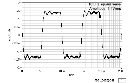
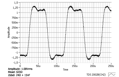
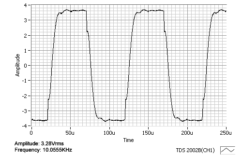
I am posting pics of a 10KHz squarewave without the zobel and with the zobel (24 ohms in series with 15nF).
Here you are....
Although it may be an interesting mental math skill exercise (sort of like solving a crossword puzzle), one cannot calculate the required RC network without
all the parameters including strays included. After you do all the exacting measurements that are required to derive the values for the model, and then do all the math, you will still need to adjust the values of the R and C in the lab for optimal response.
Dale's procedure spelled out in the Jensen document is very close to my own. When I designed the JT-xx series of tranformers at Jensen, I had to determine hundreds of optimal RC damping networks. What Dale didn't explain is that we really didn't use a capacitor substitution box. We had a kludge board with an air-core variable capacitor -like those used to tune in old-time vacuum-tube radios. This makes a variable capacitor of maye 50 pF to 500 pF which covers a pretty wide range of values. We switched in fixed caps in parallel to make bigger values. In series with the variable capacitor(s) were 3 pots connected in series -- A 100k, 10k and a 1K in order to fine tune any value from 0 Ohms to 111kOhm.
It is important that you watch the square wave on the scope while you diddle the values -- a lot like playing a video game. You adjust both R and C for the fastest risetime and sharpest corner with no overshoot and ringing.
If the transformer has more than one resonance, you may not be able to get them all damped. You can try two different networks in parallel, but really you should get a different transformer. Transformers with more than one resonant frequency generally never sound as good as one, because every musical transient excites both resonances and the resulting intermodulation distortion generates very ugly and non-musically related sum and difference frequencies. I had to work really hard to design out any multiple frequency resonances in my Jensen transformer designs.
Once you get a good looking square wave, measure the capacitance with a C meter and solder in the closest 5%standard value. Then use the variable resistor(s) to re-tweak the network for best response with that capacitor. Since 1% resistors come in much finer steps than caps, you can usually get a standard value resistor that gives really good results. Finally sub in a real resistor which will have less strays than a pot and make sure the square waves still looks great.
The scope photos that you show are of a problem transformer. The 620 Ohm load resistor has already tamed the major resonance. Note that the only ringing left is at about 100 kHz and it looks like a secondary resonance to me.
The second photo shows an incorrect RC network Your capacitor is too big. Your resistor is too small. The single low-frequency bump is your capacitor resonating the transformer leakage inductance and making it overshoot. The resistor is too low so instead of the network acting like an additional resistive load that kicks in only at HF, it is allowing the big C to be in parallel with the secondary thus resonating the transformer. You have reduced the HF bandwidth and made a big peak in the HF response. I predict that this particular transformer will sound better without your network. You may be able to find one that works, but the ringing frequency is really low and will probably be very hard to damp. This is the kind of transformer I would have never allowed to become a final product, but I would have tweaked the insides of the transformer to fix the ringing.
If you really want a nightmare -- try putting a cap across the secondary that simulates cable capacitance -- say 33pf/foot x 100ft = 3300pF. The overshoot you will get will be very frustrating as the cable C interacts with the relatively high leakage inductance.
Output transformers must have extraordinarily low leakage inductance to not be affected by cable capacitance. That's why Jensen output transformers are multi-filar construction which gives very low leakage inductance and resulting insensitivity to load and cable capacitance.
Using a resistive pad at the output of your transformer (assuming that the amplifier has the headroom) may allow you to isolate the secondary from cable capacitance and minimize the cable induced resonance.
Many of the "vintage" transformers had lower bandwidth than modern ones. Also, the Miller capacitance of many vacuum tube circuits is there but not on the schematic.
Having the proper RC network on the secondary of a tranformer that requires it, is critical to the sound of the audio circuit that it is married to. The high frequency ringing, if passed on to the following amplifier stage will ask the amplifier to follow the high frequency garbage precisely, and the amplifier has little feedback and running out of slew rate at those frequencies. The amplifier, as a result, ends up putting out significantly more ugly intermod distortion than it would if the HF ringing was passively damped before ever reaching the following amplifier.


![Electronics Soldering Iron Kit, [Upgraded] Soldering Iron 110V 90W LCD Digital Portable Soldering Kit 180-480℃(356-896℉), Welding Tool with ON/OFF Switch, Auto-sleep, Thermostatic Design](https://m.media-amazon.com/images/I/41gRDnlyfJS._SL500_.jpg)


