Damping transformer ringing (Zobel network question)

GroupDIY Audio Forum

Help Support GroupDIY Audio Forum:

This site may earn a commission from merchant affiliate links, including eBay, Amazon, and others.
Why is it that manufacturers of transformers don't suggest Zobel + Loading resistor values to prevent ringing? Is it something they don't like to talk about? I guess the x-formers are intended to be used with a variety of input impedances, so it's tricky to have a 'one suits all' method?

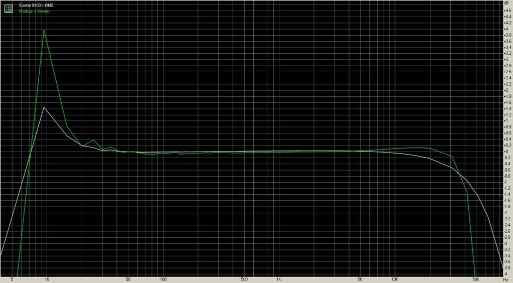
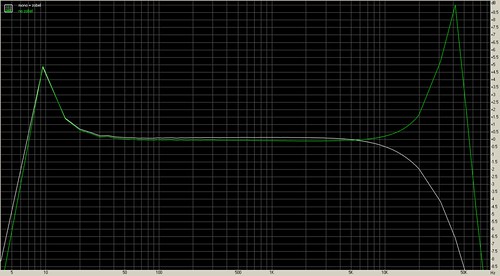
In my experience, the cheaper the transformer, the worst the ringing - with one or two exceptions. I find the OEP transformers from RS / Rapid etc to be terrible in this regard. Expensive transformers from the likes of Lundahl seem to exhibit near to zero ringing.

I've seen complete circuits exhibit good THD performance with a ringing transformer, but measure very poorly in terms of IMD - which would support Steve's excellent points.


Justin

edit - Sowter offer Zobel values in their data, but I don't recall many other OEMs being so liberal with such info.


This shows a 600:600 OEP transformer without Zobel. The next step is to start the procedure outlined in the Jensen article and see what improvements can be made.

http://www.rapidonline.com/netalogue/specs/88-2108.pdf

Justin
 
Hi,

Thank you for your reply.
Your last picture looks like the Sowter trafo (1:4) with the wrong termination (I used 68K).
When I put the correct value (10K), ringing almost disappears.

I don't know if oep does the same.

Output transformer was wounded using m6 lams, and 5 sections: 3 for prim., 2 for sec. (iirc).

Any hints to improve leakage inductance?
#
#
 
Same OEP transformer, no Zobel @ 5k


With Zobel @ 5k


No Zobel @ 10k


With Zobel @ 10k


This was achieved via the 'Roche' method posted earlier in the thread - many thanks!

Unfortunately, I couldn't get a straight edge with any cap lower than 22n in value. Whenever I went lower, I got a kink on the leading edge, regardless of resistor value.

The downside to using such a large cap is slow roll-off in the HF response:

-0.3 dB @ 10k
-1.6 dB @ 20k

I haven't taken a full FFT yet - this was just measured @ 2 points above 0dB @ 1k.

The final value was 22n + 1k8. I have a variety of other transformers to experiment with, my suspicion being that the OEP shown here is a pretty cheap transformer, and more expensive units from the likes of Sowter are unlikely to need such a large cap value. 22n does strike me as pretty large. Some transformers I've seen pass a pretty good square without a Zobel.

My tip is to print off Dale's technique and put it on the workshop wall. A real gem of a tutorial if ever there were one.


Justin

btw - I also experimented with loading resistors across the secondary with the Zobel. They didn't enable me to use a smaller cap value, and curtailed the HF even more. What you see above is achieved via a 22n / 1k8 Zobel with no parallel resistor, feeding a 4u7 film cap, driving 100k input resistance.

The tests were done via an oscillator with a 50R output. 
 
thermionic said:
The tests were done via an oscillator with a 50R output. 

Were you testing this as a line input or mic input? You may find that the HF roll-off becomes worse with higher impedance microphones. Sometimes it's good to compromise a little ring for extended response.

Perhaps more concerning though is the low-end response of these OEP transformers as documented earlier today.
 
Hi Roddy,

I'm using it for line-level apps. I can't remember exact code, but it's a 600R - 600R 1+1 / 1+1 unit.

Here's an FFT comparing its performance with and without Zobel:
3486161289_9ae489280e.jpg


Surprisingly, IMD doesn't seem to measure lower with the Zobel... Well, 0.004% better... For the entire 5-band LC EQ, from I-O (Carnhill O/P transformer) IMD measures 0.065% (0.069 minus Zobel). It does seem to sound smoother with Zobel, but that could be due to HF roll-off.


Cheers,
Justin
 
Val_r said:
Hi,

Surfing the net trying to find some article on how to correctly damp transformer ringing, I came across this page.
I think it has some error in it: I tried to calculate the Ro, with no correspondence with the calculations in the text.
What's wrong?

The site cites the following textbook:
"Design Techniques for Preventing Input-Filter Oscillations in Switched-Mode Regulators",
Did anyone experienced it? Any link to a pdf?

Thanks.
::)
You have to look at the system (the transformer, the source and the preamp) as a low pass filter. Just like in a loudspeaker cross-over, you need to install a Zobel across the speakers (to compensate for the rising impedance due to the leakage inductance). The output impedance of a loaded xfmr is essentially a resistor in series with an inductance. If you place an equal resistance in series with a cap, you can make the whole network purely resistive; inductance Ll and Req determine characteristic frequency, then use it to tune the cap versus leakage inductance. see pic
 

Attachments

  • zobel.jpg
    zobel.jpg
    98.3 KB · Views: 310
Wonderfully explained reading on Zobel's here , thanks.  I've been waiting on something
written in simplistic terms and easy to understand.

 
Sowter 8403:

When loaded with a 600R, no Zobel is needed. However, the HF rolls off pretty radically. I suspect a good compromise would be to use a combination of loading with a Zobel. Driving loads higher than it's designed to see (i.e. 10K) I can get the 8403 flat to 25k and virtually flat to 50k with just a 10n + 1k8 Zobel. Its HF response with 600R loading alone is not this good. 

As you can see from the attached FFT, the Zobel doesn't seem to cause any noticeable roll-off below 50k. If anything, I could probably increase the Zobel as there's a tiny amount of ringing compared to the unbalanced plot.

What does bug me, and can also be seen on the previous FFT with the OEP transformer, is the 4dB peak at 9 Hz... I wonder if that's an anomaly with my soundcard's balanced inputs? The humps seem to closely mirror each other's profile on the OEP and Sowter...hmmm....


Cheers,
Justin

UnbalancedVsSowter.jpg
 
What's your source impedance?

Some of that ring may go-away with a non-zero source. Some old interstages were wound with iron wire as a cheap way to insert resistance without raising winding-cost.

The 9Hz bump may be a couple 47uFd caps on your sound card output causing rising impedance below the audio band, and resonance with the transformer inductance.

 
Whereas the OEP which has a mirror bump was being used as an Input t/former, being fed directly from my RME soundcard (I'm not sure what kind of caps the RME has on its O/P), the Sowter O/P t/former shown in the later post is being driven by a Wolfson DAC eval board. I noticed 2.5v DC coming from each leg of the Wolfson's balanced o/p, so I put a 25v / 470uF cap in series with each leg.

I can't seem to find a spec from Wolfson regarding the o/p impedance of their card. I doubt it's lower than my 50R bench oscillator, and I didn't detect a resonance when sweeping the Sowter into my 'scope on the bench.

The fact that the peak is mirrored, whether driven by RME's buffer or Wolfson's, tends to suggest an anomaly with the card, wouldn't you say?

As ever, I'm grateful for your thought-provoking post, PRR :guinness:


Justin

BTW - Does anyone think this thread might get more traffic in the Drawing Board?
 
This LF peak is consistent with the expected resonance of the LCR network typical of a soundcard, but you say the peak is the same with zero output impedance and 235 uF in series; this is puzzling...there should be a difference...
 

Attachments

  • xfmr resonance with cap.jpg
    xfmr resonance with cap.jpg
    156.8 KB · Views: 169
Thanks for your input, Abbey.

I just did an I-to-O loop test on the RME and the response is flat.

What intrigues me is the way that both the OEP Input t/former and the Sowter 8403 Output t/former both mirror each other with the hump - down to minute detail.

I *believe* the RME uses cross-coupled outputs. It's TRS, and Cold can be shorted to GND, so I don't know how else they'd do this. Having said that, on the OEP example the t/f is being fed by the RME; whereas the Sowter is feeding the RME driven by Wolfson's buffer.

Hmm....

For interest's sake, here's the distortion figures:

RME + Wolfson via electronic unbalanced output = 0.0010 THD - 0.0023 IMD (RME never goes below this figure for IMD on anything)

RME Loop test via Balanced = 0.0021% THD - 0.0026 IMD

RME A-D + Wolfson D-A + Sowter 8403 = 0.053% THD - 0.107 IMD

Does the distortion figure strike you as high for the Sowter? IMD is stonking. I've never measured a modern transformer that's this high before... I wonder if I could've magnetised it. However, this could only have happened by connecting 2.5v DC to one side and my 1-Meg-Ohm meter to the other side. Not a lot of current, is it?

In terms of distortion, there's always the question of the Wolfson's buffer IC being happy to drive the Sowter. Having said that, I'd have thought there'd be more FR anomalies.

What I haven't done is purely to drive the Sowter via the RME alone. I can't imagine RME using better buffers than Wolfson's eval board for their flagship D-A though.

Justin

edit - these measurements are definitely fishy. I've just looked at a 5-band LC EQ that I measured, with OEP for Input and Carnhill for Output. THD is suspiciously low @ 0.0015 and IMD is 0.056. I can't see how an LC EQ with twice the transformers can measure better than a single transformer connected to a DAC...
 
thermionic said:
What intrigues me is the way that both the OEP Input t/former and the Sowter 8403 Output t/former both mirror each other with the hump - down to minute detail.
This is not really a surprise since OEP and Sowter tend to have some similarly designed products because they are tending to the same customers.
Does the distortion figure strike you as high for the Sowter? IMD is stonking. I've never measured a modern transformer that's this high before... I wonder if I could've magnetised it. However, this could only have happened by connecting 2.5v DC to one side and my 1-Meg-Ohm meter to the other side. Not a lot of current, is it?
This cannot magnetize the iron in a significant way. It could have been magnetized any time for several reasons. There may be some DC offset at the Wolfson's output also. But I don't think the explanation lies there. I believe the Wolfson/xfmr combo doesn't work well, or the measurement is flawed. The Wolfson's bal output is taken before the final LPF, so there may be some HF noise residual. It is impossible to conclude anything now; lack of additional data...
In terms of distortion, there's always the question of the Wolfson's buffer IC being happy to drive the Sowter. Having said that, I'd have thought there'd be more FR anomalies.
Not necessarily. The FR of a xfmr in combination with its environment is very predictable. It is a minimum-phase system with well defined parameters
What I haven't done is purely to drive the Sowter via the RME alone.
You need to do that. First rule of scientific examination: change ONE parameter at a time.
 
Ok, I've taken full measurements of the Sowter 8403 with same Zobel values, taken between the I/O of the RME with nothing else in the chain. As you can see, the peak around 9hz is still there, but it's much smaller. THD is much better. IMD is still uncomfortably high, but under half the amount that I was getting when the 8403 was being driven by the Wolfson alone.

THD - 0.014
IMD - 0.040

It does appear that both the RME and the Wolfson aren't too happy about driving the 8403.

The next experiment should be to take a discrete op-amp with high-current output drivers, wired for unity, and put it in front of the 8403, but still using the RME I/O.

Thanks again, Abbey.


Justin

WolsonwithSowtervsSowterRME.jpg


Hi,

Attached is a comparison between all 3 stages (discrete op-amp in white) that have driven the Sowter 8403.

Note that the slight peak between 7.5k and 15k is mirrored by both the Wolfson and the DOA, but not present when the transformer is tested alone with the RME. Both the DOA and the Wolfson have a 470uF blocking cap feeding the transformer. The same Zobel is used on all 3 tests.

Distortion via the DOA is:

THD = 0.0085
IMD = 0.013

IMD and distortion are roughly 70% lower when you buffer the RME’s output with the DOA. I ended up setting the DOA for around 10dB gain. This was a pretty crude test, and I reckon I could get the distortion down far more for the DOA. I have measured the same DOA before minus transformer and it’s been below the RME’s distortion floor.

The crucial thing to note is that, when the Sowter 8403 is driven by the DOA, it has a smooth LF contour that’s 0.2dB down by 20hz and rolls off  gently – with no 9hz peak like when the RME or Wolfson are driving it.

Cheers,
Justin

DOAvsRMEvsWolfson.jpg
 
Attached are shots of the DOA feeding the Sowter 8403  - and with the t/former bypassed, DOA feeding A-D of my card. As can be seen, there's a resonant peak around 9hz with the DOA driving the transformer.

Distortion rises from 0.0011 (no t/former) to 0.018

IMD rises from 0.0020 (no t/former) to 0.039

The question in my mind is, if I manage to tame the LF peak, will the distortion be affected? I like the 8403 subjectively, but I'm surprised to see how large the distortion is.

Transformer is white trace, green is just capacitor to A-D card.


FR
NoTransformervsWithTransformer.png

 
THD - DOA with and without T/former
 

Attachments

  • No Tx vs With Tx - THD.png
    No Tx vs With Tx - THD.png
    18.1 KB · Views: 98
Your measurements are not surprising at all, the 9Hz boost is accompanied with a rise in magnetic induction in the xfmr that also increases distortion. However, keep in mind that in most musical applications, there's not much energy below 30Hz, so this should not be a practical problem. But this shows that there is a big difference between sticking a xfmr to an existing output stage and designing a proper xfmr-based output stage. If you feel that 9Hz is too close to your expected LF extension, you should increase the value of the coupling caps.
 
If you feel that 9Hz is too close to your expected LF extension, you should increase the value of the coupling caps.

I've never felt that anything below 20hz is going to affect my results, it's just that it doesn't look very pretty on the FFT. I will be trying larger caps. I can't see it having an audible difference, but I will have peace of mind. I'll be interested to see if the larger caps calm the peak and affect IMD though.

Thanks,

Justin
 
Back
Top