DB25 summing PCB - MK2??

GroupDIY Audio Forum

Help Support GroupDIY Audio Forum:

This site may earn a commission from merchant affiliate links, including eBay, Amazon, and others.
bruce0 said:
I would like to see a 2 space 500 module, with 2 Dsub25 boards mounted on the faceplate.

Those will fit with JLM audio INX5 500 series dingo cards, which can be pretty easily configured for virtual earth summing, with a second stage to re-invert (with or without transformers) and adjustable gain.

Then a spot for 2 Gain knobs or a concentric one for left and right or gain and balance.

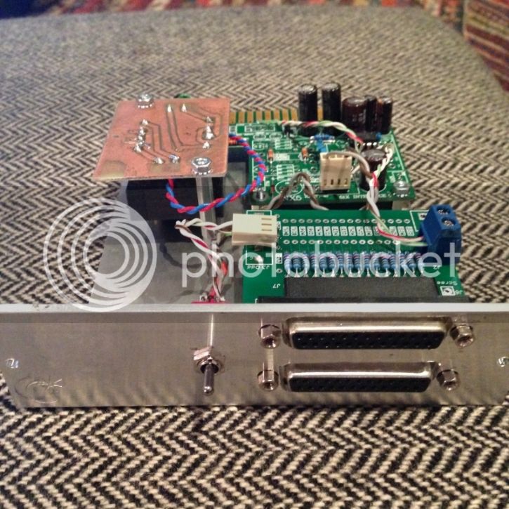
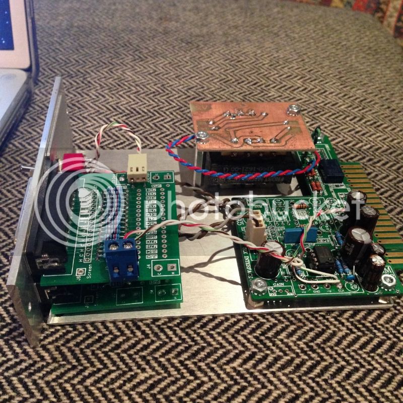
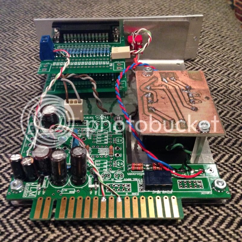
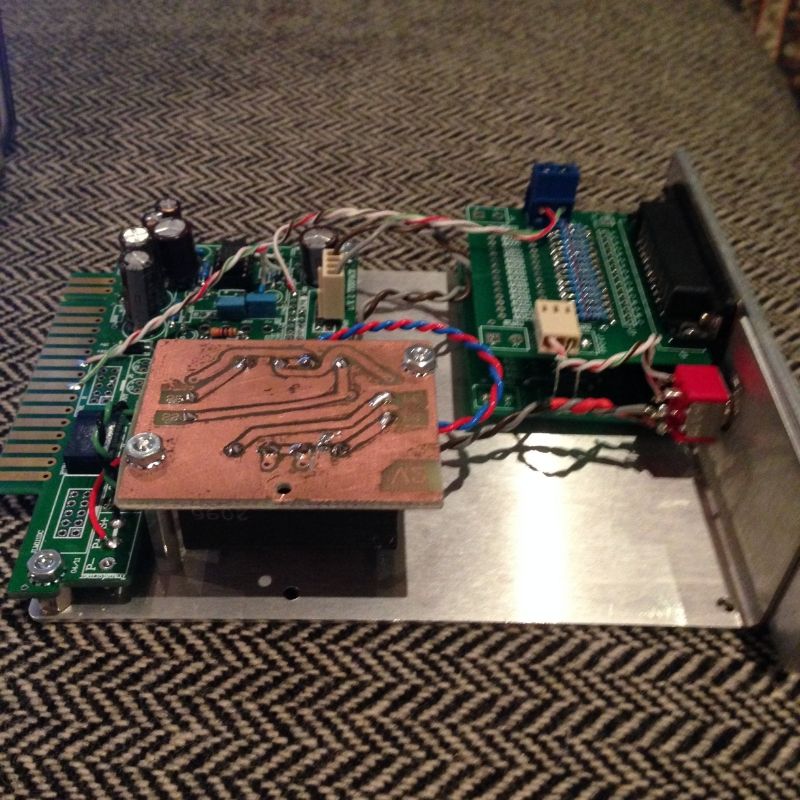
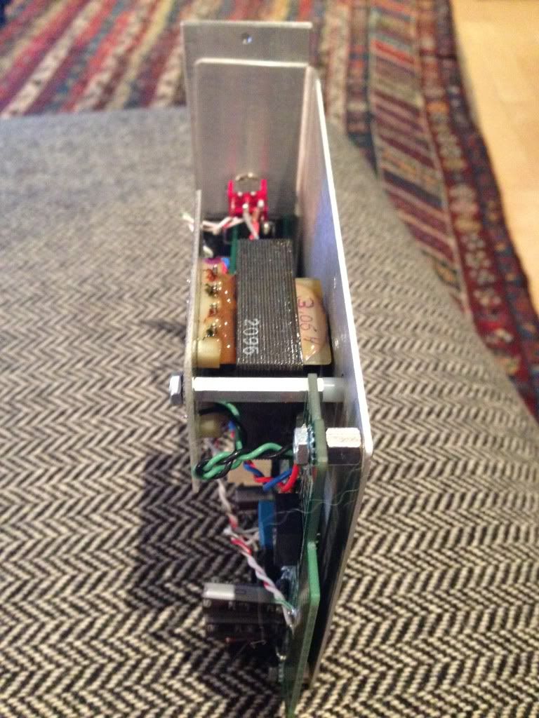
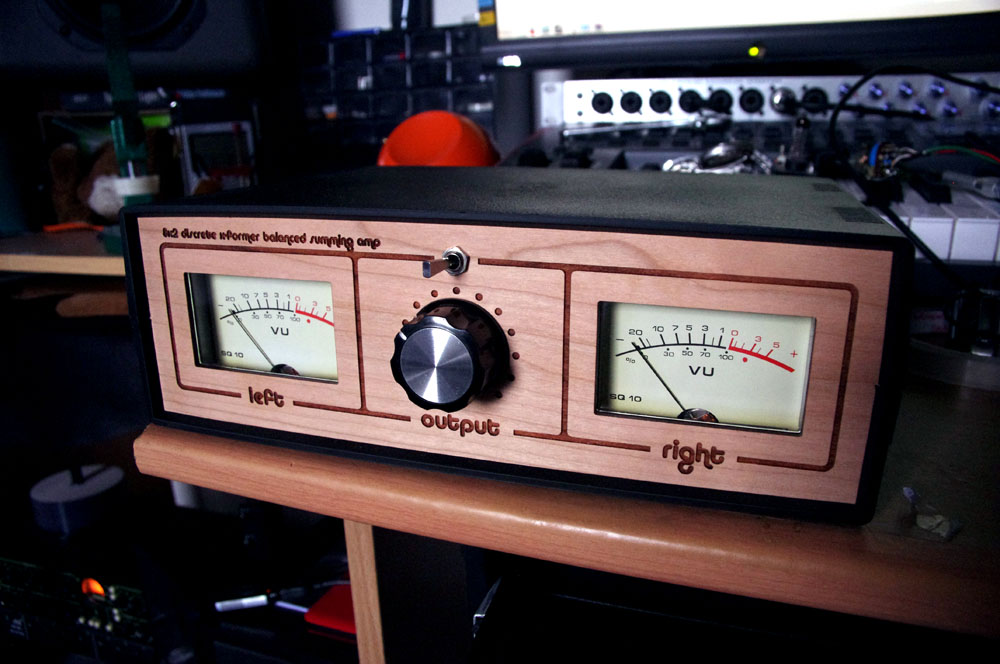
The boards fit, that is what I am building now, but would love to have faceplates.

My plan is to make it 16 channel summing, and have the gain knobs have switched positions based upon the number of active channels (gain changes with different numbers of channels).

I figured 18 channels (I was planning to wire in the back two inputs manually).  The outputs are on the back.

But I realize this is a little "500 specific".

I have measured, and your cards will fit in front of the INX5 cards.

Prototyping now, will post pics when done... behind a few projects.

b

I would like to see pictures of your build.  Can you draw a schematic of how you configured the INX5 cards?  What did you use for output transformers?

Audiohammer
 
Hammer

Sorry project stalled behind other projects and a Blue cruise in turkey.. (Actually not so sorry  (grin) but I do apologize  8).

There are comments on the JLM site build forum ( for the DINGO build i think which is pretty much the same schem as the INX5) about how to strap / jumper the PCb as a virtual earth amp for summing

The guidance is not super clear, the card has an input debalance section and an output section and as I remember one can make the input section inverting for a virtual earth summer ( because the design is non inverting you have to put a couple of straps on the card but you can do it.)  I was going to use the output section as is and use the transformers to re-invert, but you probably could get the output section to do the re-inversion.

It is a bit "fiddly" but I think it will make the 500 card edge simple and let me do it with no etching and let me fit the Trafo ( though the inx5 card does not have holes for mounting trafo ( Too bad) it does have a space and I was thinking of bolting the trafo to the L bracket.

I was going to use some a 1:1 600 ohm trafos I have.
 
So I threw this together, based on Ian's board(saved me so much screwing around, thank you!) with API 2520 style make up gain and yamaha tamura transformers on the input and output of the 2520 opamps.

Excuse the rats nest. I just finished calibrating the VU meters.

front.jpg


back.jpg


inside.jpg


vulights.jpg
 
@Humner,

Love the enclosure! Looks like plastic from the outside but like aluminium on the inside. I especially like the real wood front and rear panels. Who makes the enclosure?

Cheers

Ian
 
ruffrecords said:
@Humner,

Love the enclosure! Looks like plastic from the outside but like aluminium on the inside. I especially like the real wood front and rear panels. Who makes the enclosure?

Cheers

Ian

Thanks. The enclosure is plastic - it comes in white/light grey, which I sprayed black. I'm based in Australia and I buy them from here - http://www.jaycar.com.au/productView.asp?ID=HB5910&form=CAT2&SUBCATID=986#1

The wooden panels are laser etched 3mm cherrywood which are made separately. I created the design in AutoCAD which is then sent for laser etching. The panels just slide in where the black plastic panels would go from the stock enclosure.

Rob
 
AudioHammer said:
I would like to see pictures of your build.  Can you draw a schematic of how you configured the INX5 cards?  What did you use for output transformers?

Audiohammer

Back from the Mediterranean (great trip with the only low point being that Istanbul did not get the Olympics, which is too bad because I think that might have helped bring the world closer together).  So I am beginning to dig through my "eyes are bigger than my soldering iron" projects... and the "tascam summer" is on top.

I decided to make a left channel and a right channel. Each a single space 500 card, using the JLM INX5 Dingo card with modifications.

Each channel will have 16 or 17 inputs (2 DB 25 cards at 8 each, and possibly the back input as well if I can hand wire it).  These cannot quite fit vertically but I think I can fit them either angled or side by side.

I mod the INX5 card pretty dramatically, using very little of it's capability and only use the power input and output driver stage.  Further this mod requires that I use a dual monolythic opamp (can't use the DOA's must use a NE5532 or OPA2604 or similar) because i need both halves.  The mod turns the output stage into two separate virtual earth amplifiers one on Ian's Hot and one on Cold, and run those outputs to the two sides of an output transformer (600:600).  My hope is that ground noise picked up on one will also be picked up on the other, and thus cancel each other out.

I am using 2 cards, using only the Odd Summing Bus, daisy changed between the two DB25 cards.

I am using 6.2K resistors (12.4K input impedance on each channel), and the feedback resistors marked in orange on the schematic are 12.4K (approx.), so I am hoping it will be unity gain ish.


Hopefully someone with better sense than me will let me know if I have gone wrong somewhere here.  My questions are:

1) Did I screw up on the modification?
2) Will the gain come out right?
3) Will the ground noise cancellation work?
4) Are the values for resistors rational?
5) Ian makes a provision for a shunt resistors on the bus, what overall impedance should I shoot for for a NE5532? For a OPA2604? 
6) I think the capacitors C7 and the new one on the other channel can be anything from about 47uF up but are they required at all?

INX5schematicsummerwithtrafo_zps7aeaa7c7.jpg


bruce0 said:
I decided to make a left channel and a right channel. Each a single space 500 card, using the JLM INX5 Dingo card with modifications.

Each channel will have 16 or 17 inputs (2 DB 25 cards at 8 each, and possibly the back input as well if I can hand wire it).  These cannot quite fit vertically but I think I can fit them either angled or side by side.

I mod the INX5 card pretty dramatically, using very little of it's capability and only use the power input and output driver stage.  Further this mod requires that I use a dual monolythic opamp (can't use the DOA's must use a NE5532 or OPA2604 or similar) because i need both halves.  The mod turns the output stage into two separate virtual earth amplifiers one on Ian's Hot and one on Cold, and run those outputs to the two sides of an output transformer (600:600).  My hope is that ground noise picked up on one will also be picked up on the other, and thus cancel each other out.

I am using 2 cards, using only the Odd Summing Bus, daisy changed between the two DB25 cards.

I am using 6.2K resistors (12.4K input impedance on each channel), and the feedback resistors marked in orange on the schematic are 12.4K (approx.), so I am hoping it will be unity gain ish.


Hopefully someone with better sense than me will let me know if I have gone wrong somewhere here.  My questions are:

1) Did I screw up on the modification?
2) Will the gain come out right?
3) Will the ground noise cancellation work?
4) Are the values for resistors rational?
5) Ian makes a provision for a shunt resistors on the bus, what overall impedance should I shoot for for a NE5532? For a OPA2604? 
6) I think the capacitors C7 and the new one on the other channel can be anything from about 47uF up but are they required at all?

1. Looks basically OK to me. Yo are using virtual earth summing rather than passive.
2. It's a virtual earth so it ought to.
3. It's balanced throughout so it will be as good as the worst CMMR. That could be set by gain differences between hot and cold channels for instance.
4. Look OK to me.
5. The shunt resistors are only needed if you use passive mixing so you don't need them.
6. The cap is effectively in series with each 6.2K resistor so choose its value to set you -3dB point at about 3Hz for minimum phase shift at 20Hz. 47uF gives you a -3dB point at about 0.5Hz.

Good luck.

Cheers

Ian
 
ruffrecords said:
bruce0 said:
1) Did I screw up on the modification?
2) Will the gain come out right?
3) Will the ground noise cancellation work?
4) Are the values for resistors rational?
5) Ian makes a provision for a shunt resistors on the bus, what overall impedance should I shoot for for a NE5532? For a OPA2604? 
6) I think the capacitors C7 and the new one on the other channel can be anything from about 47uF up but are they required at all?

1. Looks basically OK to me. Yo are using virtual earth summing rather than passive.
2. It's a virtual earth so it ought to.
3. It's balanced throughout so it will be as good as the worst CMMR. That could be set by gain differences between hot and cold channels for instance.
4. Look OK to me.
5. The shunt resistors are only needed if you use passive mixing so you don't need them.
6. The cap is effectively in series with each 6.2K resistor so choose its value to set you -3dB point at about 3Hz for minimum phase shift at 20Hz. 47uF gives you a -3dB point at about 0.5Hz.

Good luck.

Cheers

Ian

Ian:

Thanks! 
On #3, good point, that had not occurred to me, and I guess if I plugged an unbalanced signal in that would change the gain on that side and change the gain.

On #5, I understood that the internal noise of the NE5532 is higher if the impedance is too high, but I am not sure how to calculate that (got this idea from Fred Forsell's summing article).

On #6, I think since it is balanced the cap is in series with 12.4K (both summing resistors) paralleled together for as many active channels as exist (so with 16 channels active and assuming output impedance of 0R it would be 775R (so a 4.4Hz knee).

One comment that is a bit confusing is the idea that Virtual Earth is not passive summing. Is the notion behind passive summing that it needs to be amplified through a non-inverting amp?  I suppose I could make the output just be the sum and then (with an appropriate shunt) run that into a pair of mic preamp inputs.  I didn't know what the advantage of this was and if you can explain I would appreciate it.

My goal for this project is to try out passive summing to replace the in-the-box summing that I currently do.  I was going to sum stems, or possibly individual channels out of my DAW ( I have 16 pretty good output channels I can sum) and see what the results were.  If I would be better off with "pure passive" I suppose I could try to rig up the bypass  relay on the INX5 to let me experiment with that.  Click into bypass for a pure passive sum and then run it into a pair of mic preamps ( I could even probably figure a way to relay in the shunt).

Any thoughts appreciated

 
bruce0 said:
Ian:

Thanks! 
On #3, good point, that had not occurred to me, and I guess if I plugged an unbalanced signal in that would change the gain on that side and change the gain.

It would only change the gain for that input.
On #5, I understood that the internal noise of the NE5532 is higher if the impedance is too high, but I am not sure how to calculate that (got this idea from Fred Forsell's summing article).

That's a very complicated topic but in this instance the impedance is set by the summing resistor and feedback resistor values and their values are determined by other factors. Slugging the bus would reduce the impedance BUT it would worsen the noise performance because it would increase the noise gain.

On #6, I think since it is balanced the cap is in series with 12.4K (both summing resistors) paralleled together for as many active channels as exist (so with 16 channels active and assuming output impedance of 0R it would be 775R (so a 4.4Hz knee).

We'll just have to agree to disagree for the moment. I'll do a simulation to (hopefully) demonstrate that I am right  ;)

One comment that is a bit confusing is the idea that Virtual Earth is not passive summing. Is the notion behind passive summing that it needs to be amplified through a non-inverting amp?  I suppose I could make the output just be the sum and then (with an appropriate shunt) run that into a pair of mic preamp inputs.  I didn't know what the advantage of this was and if you can explain I would appreciate it.

I thought Fred's article made it fairly clear what the difference is. Another way to think of it is that passive summing is effectively voltage summing and VE summing is current summing. In passive summing, each output sees a pot divider consisting of its own bus resistor and the parallel sum of all the other bus feed resistors to ground. All of these potted down signal voltages add up across the bus impedance which is why I say it is voltage summing. So if you have N channels, the attenuation each one sees is 1/N and you need a gain make up amplifier with a gain of N to get unity gain overall. You can do this with a non inverting amplifier but it is not essential; any amplifier with a gain of N will do but a non inverting type is probably the least noisy way of doing it.

In a VE mixer, the + input is grounded. The feedback to the - input therefore tries to keep the - input at the same potential as the + input i.e. ground or earth - hence the name. To do this the current flowing through the feedback resistor must be equal and opposite to the sum of all the currents flowing in from the bus resistors which is why I say it is current summing.. Of course, the sum of currents flowing in the feedback resistor produces a voltage at the output equal to the sum of all the input voltages so the effect is the same as a passive mixer.

My goal for this project is to try out passive summing to replace the in-the-box summing that I currently do.  I was going to sum stems, or possibly individual channels out of my DAW ( I have 16 pretty good output channels I can sum) and see what the results were.  If I would be better off with "pure passive" I suppose I could try to rig up the bypass  relay on the INX5 to let me experiment with that.  Click into bypass for a pure passive sum and then run it into a pair of mic preamps ( I could even probably figure a way to relay in the shunt).

Any thoughts appreciated

Well, either way you are doing true analogue summing whether its VE or passive. I am not sure there's a huge amount to choose between them. Passive can be extremely simple if you use an external mic pre but if you want to build a stand alone box with +4dBu output then you will need an amplifier of some kind.

Cheers

Ian
 
Ok, thanks!  I guess I will solder first, learn and think second! (I can't believe I said that).
 
Ok, no pictures but the first thing I learned is that it is difficult to mount a D-SUB connector in a 1/8" aluminum faceplate with L-Bracket.  (I found a cheap DSUB punch on ebay (nobody outbid me please) so that may help but the first attempt with dremel left the Jack screws too far out. ) So I had to machine deep holes to hold the screws, and cut the L Bracket so that the Summing cards mount directly to the faceplate and that worked.  Got my DB25 connectors off of old modem cards I picked up for $1 each and unsoldered (it is important to re-use!). I will post pics.

I am using the INX5 board as a balanced virtual earth amp, but because of Ian's suggestions I am making the bypass relay switch in a shunt resistor and switch out the amps.  So I can use it as a passive summer, or an Active summer with the switch of a flip.  More later.
 
bruce0 said:
Ok, no pictures but the first thing I learned is that it is difficult to mount a D-SUB connector in a 1/8" aluminum faceplate with L-Bracket.  (I found a cheap DSUB punch on ebay (nobody outbid me please) so that may help but the first attempt with dremel left the Jack screws too far out. ) So I had to machine deep holes to hold the screws, and cut the L Bracket so that the Summing cards mount directly to the faceplate and that worked.

Cutting out odd shaped holes is a real PITA. I recently had to cut out a hole for a combined mains inlet/switch/fuse/filter for my demo mixer. It was a big rectangular shaped hole and to make it worse I had to make it in a steel plate. I drew the shape on the plate in pencil, drilled loads of 3mm holes all around the edge, then used a needle file and junior hacksaw to roughly cut out the hole. Lastly the big file came out to create the final shape. A good hour's work just from one hole.

Cheers

Ian
 
Added pictures, and did some testing.  A problem has emerged.

I set up the Summing card with a DPDT switch (passive / active ) that switches in a shunt when the switch is turned to passive, and opens when it is in active simultaneously activating a relay to use the INX5 amps (virtual earth). 

The problem is that I don't disconnect the virtual earth when I switch, so that when the card is powered the amps drag the inputs to ground in passive mode. 

Works great if I don't power the amp.  And works great if I power it in active mode.

I was wondering if I could put a resistor inline with the virtual ground inputs to fix this?

null_zpsb02f6f00.jpg


null_zps634916c3.jpg


null_zpsfa282310.jpg


null_zpsb0b53768.jpg


null_zps93456bee.jpg


null_zps99d8e830.jpg
 
Very cool!  Assuming this one 500/51X series card is for the left side mix, Is that going to be 16 inputs for the left side or will the 8 inputs from the second DB25 connect to another INX5 pcb for the right side sum?

What op-amp are you using?  How does it sound?  Any noise issues?

:)
 
I am building two of them.  So I will be able to sum 16 left channels and 16 right channels.  There is no provision for panning or assigning.

I am using a OPA-2604 currently, because (I think.. but am not sure) the bus impedance is too high for at 5532.

The summing resistors are 6200R (so each summed channel sees 12.4K impedance balanced).  The hot side and the cold side of each balanced channel are summed using a virtual earth inverting op-amp.  Since I usually will be summing less than 16 channels (8 left and 8 right) the typical impedance will be greater than 775R per bus (hot bus and cold bus).  I drive a transformer with the outputs of those inverting opamps on either end of the primary winding. 

Anyway, I don't know how it sounds yet, I have only got it on a scope.  As I said in the earlier post I have a problem.  I put a switch in to make it so that I could do summing into a mic pre with the same module.  It takes the transformer out of the circuit and drops a shunt resistor across it.  But the problem is that because the virtual earth amps are virtually ground it is like it grounds out both busses.

I am wondering if I could put a series resistance AFTER the bus leading into the virtual earth amp, but I don't know what effect that would have or how high that resistance can be.  Any help on that would be appreciated.  Attached is a schematic.
 

Attachments

  • INX5 schematic editable jpeg.jpg
    INX5 schematic editable jpeg.jpg
    610 KB · Views: 81
Brian, I was wondering if I put say a 1K resistor in series with the opamp inverting input on both opamps, then they would not drag the buses to ground.  But if that is a bad idea (adds too much noise? attenuates the bus too much?)

I have some little DPST relays lying around, I could probably disconnect the inputs when I disconnect the outputs.  But I will have to just hot glue the relay somewhere.
 
Back
Top