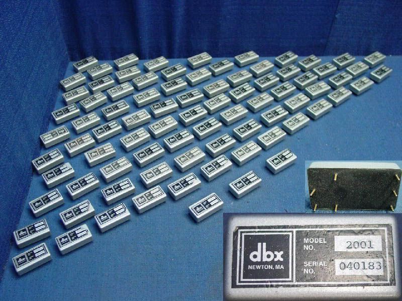
DBX 2001 VCA

GroupDIY Audio Forum

Help Support GroupDIY Audio Forum:

This site may earn a commission from merchant affiliate links, including eBay, Amazon, and others.

CJ

Well-known member
GDIY Supporter
Joined
Jun 3, 2004
Messages
15,755
Location
California
There has been some Top Secret behind the scenes cladestine operations going on around here by who knows who. They are trying to bootleg this primitive discrete VCA because they are retro to the bone. Seems foolish to me, as we now have laser trimmed, THAT VCA's that put out 1/1000 th the distorton and function like nobody's bidness. But, just for posterity, I think it would be cool to understand how these new-fangled chips work by taking a look at one of it's predescorrsreesesrs. So here is a DBX 2001 schematic. And there is a circuit description to follow for those who understand these transistor thingys. There was some discussion over at the Constant Current thread on a few of the body parts therin. Anyway, would anybody hazzard a guess as to the value of capacitor number 60, since whoever is perfoming the patent infringent exercises accidently destroyed the markings durring said dissection, whoever that may be. Thanks!

dbx_2001_schem.gif


You can print out a circuit description here:

DBX

There is a more detailed description if anybody is interested.

Thanks!

cj
 
umm didnt I send ya a few 2001's?

I coulda swore that I did

I know I tore one a part along with a few others :)

VCA.jpg
 
you swine scen! told me ya run out! :evil:

just as well i... :grin: you aint seen me reeeeeiiighhht!

seenme2.gif
 
Anyway, would anybody hazzard a guess as to the value of capacitor number 60, since whoever is perfoming the patent infringent exercises accidently destroyed the markings durring said dissection, whoever that may be. Thanks!

I dunno, but I'll hazzard a guess on what will work. :green:

IIRC, a similar design used a fairly high value cap there (like 100 uf). It's in the old PMI databook under MAT-04 applications. Seems like it was supposed to be better to use a tantalum since it might see a low reverse voltage (don't freak, it's not in the signal chain). FWIW.
 
Hi folks. I'm new here.

The value of the capacitor in question is 1.5 nF. The schematic in the patent description is incomplete. I have a hard copy of the schematic here, and I will try to scan it and post it here. However, there are a large number of active and passive component selection procedures that are now lost.

Regards,
Gary
 
Hi Gary!
Welcome to the club!
And thanks for the value. Yes, transistor matchinfg is important for this thing. Fortunately, parts today are a lot better right out of the bin than they used to be. I have taken apart a couple of 2001's and on a few matched pairs, the matching was terrible. Maybe that's why Scenaria ended up with those. :grin:

Anyway, thanks again and looking forward to any help you can give us on DIY'ing thes things. A few people say they like the sound beter than the latest stuff. SHould be fun either way.
 
Here is one difference we noticed on the 2001 that was taken apart vs the patent schematic. Q-12, an extra transistor. Some type of mod or upgrade I presume. I do not know what it does. The emmiter goes to ground. Maybe someone here....


dbx_current_source_top.jpg
 
Folks,

I have the dbx 2001 schematic in .pdf format. Is someone willing to host it on their website?

Gary
 
CJ,

The function of Q3 in dbx schematic (Q12 in your schematic) is to keep the collectors of Q6 and Q7 at about +2 Vbe (and thus, about 0V Vcb) via negative feedback. This optimizes their match to Q10/Q11 respectively.

Similarly, CR4/Q14 keeps the collectors of Q12 and Q13 at about -2 Vbe, optimizing their match to Q8 and Q9.

All of the 8 gain-cell devices thus sit with about 0 V Vcb, though this is altered somewhat by the gain-control voltage in the case of Q9 and Q10.

Gary
 
[quote author="daArry"]you swine scen! told me ya run out! :evil:

just as well i... :grin: you aint seen me reeeeeiiighhht!

seenme2.gif
[/quote]


aww man..

I did run out..

that pic was from a few years ago..

I have a few left but they are for my ssl comp (when I ever get to building it)
 
Gary, inside a 2001 I found a 54.9 ohm resistor for R6 and a 33k for R12. R12 is listed as 10k nominal, so I guess this is a tweak done on the test bench. Probably done to dial in equal current draw I suspect?

Do you know what kind of metal tape was used to provide thermal coupling on those early VCA's ? Thanks!

cj
 
> hazzard a guess as to the value of capacitor number 60

Guessing is hazardous. That is the compensation cap for the feedback loop. You think compensating a regular amplifier is tough.... in a VCA the gain varies over a wide range. The usual compensation is just-stable at highest gain, though that leads to very low bandwidth at low gain. Or to put numbers on it: suppose the loop could be stabilized to 1MHz at maximum gain, then response at -60dB gain would only go to 1KHz. The compensation response can be calculated simply, but the parasitic poles that limit the max-gain stability depend on parts and layout, need experimentation.

1,500pFd sounds high but may be right. May very well be right: I recall 470pFd for high precision multipliers, and a good-audio multiplier would work up to higher current for better S/N at the expense of exact multiplication accuracy.

> a similar design used a fairly high value cap there (like 100 uf).

Must be a different thing. Cap 60 loads audio at a fairly high impedance point; 100uFd would be an audio short. There are so many variations of where you stuff CV and audio in and out of the quad that it is easy to get tangled.

As Gary says: patent applications are NOT building plans, and may be as unrealistic as possible while still establishing priority.

> All of the 8 gain-cell devices thus sit with about 0 V Vcb.

It needn't be zero exactly, CV shift is no big deal. It has to be very low to minimize C-B leakage and Early effect which screws-up accuracy. Actually that may be no big deal for audio, and there are audio multipliers with significant voltage on the devices. But the zero-volt condition works good, and isn't hard to arrive at.

> Yes, transistor matchinfg is important for this thing. Fortunately, parts today are a lot better right out of the bin than they used to be.

That may not be what you want.

If you are obsessed enough to build VCAs, study the difference between Class A and Class B VCA bias. Back in the VCA Wars, strong opinions about the "sound" were expressed (but also there were patent-right issues dividing the two camps). Since the patents are old and nobody will sue a small DIY project, you should explore both ways.
 
Thanks Paul!
An SSL Comp with sockets for trying different VCA's, including the latest THAT chips would be cool. The boards are small, parts count fairly low, so much fun to be had. Maybe a switch for going between different VCA's mounted on the front panel would look good on the coffee table.
Do these Class A jobs run very hot? I know from the patents that thermal is a big part of these things. I bet transistors were checked for temp characteristics as well as matching and noise.
 
Gary, inside a 2001 I found a 54.9 ohm resistor for R6 and a 33k for R12. R12 is listed as 10k nominal, so I guess this is a tweak done on the test bench. Probably done to dial in equal current draw I suspect?

R6 would nominally match R10 in parallel with R11 (if the NPNs and PNPs had identical betas and Rb's). It was selected at test to minimize THD, probably at 0 dB gain, after SYM trim. R12 adds a small version of the gain-control voltage to the symmetry correction. This compensates for the mismatch in Early voltages between the NPNs and PNPs. It would be chosen for minimum THD off 0 dB gain, such as + or - 20 dB.

The best anyone remembers about the tape is that it was aluminized mylar.

BTW - I obviously misstated the value of C1 in the schematic. It's 3.3 nF. I must have been looking at the 150 ohm resistor???


Gary
 
Back
Top