You are using an out of date browser. It may not display this or other websites correctly.
You should upgrade or use an alternative browser.
You should upgrade or use an alternative browser.
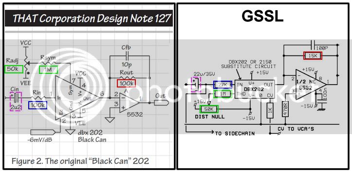
DBX 202 black can in GSSL
- Thread starter marcfrom
- Start date


Help Support GroupDIY Audio Forum:
This site may earn a commission from merchant affiliate
links, including eBay, Amazon, and others.
SSLtech
Well-known member
The ratio adjustment resistor (feedback around the op-amp) might suffice.
Value? -work it out from the 50:6 relationship, then confirm by experiment, and tell us.
I've never built one using black-cans.
Keith
Value? -work it out from the 50:6 relationship, then confirm by experiment, and tell us.
I've never built one using black-cans.
Keith
Hi Peat,
Yes i've read this thread, but Gerardmanvuca said he changed the 15k for 100k resistors and he didnt notice any diffrence in sound or level.
I have some doubt, if the VCAs (202black /gold) work with no same control tension, i think we have to adjust this tension with resistors, and measure the ratio value.
SSLtech
Well-known member
marcfrom said:Ok Keith, but do you talking about the two 15K resistors wich feedback the NE5532 (just at the ouput of the VCAs)?
Or do you talking about the 127K* that we usualy adjust to calibrate the ratio?
The 127k.
I reckon the new value will be in the 15kΩ region... Try 12kΩ with a 5kΩ trim-pot, although you might have MASSIVE makeup gain range, in which case you'd also have to reduce the feedback around the op-amp following the makeup gain pot, by about the same degree (a factor of 8.3333 etc.)
Keith
")
Harpo
Well-known member
Substituting the 127k* would be more like 1Mohm to get a 6mV/dB instead of 50mV/dB controlV and the 620k at the makeup pot would need a sizeup as well. I'd probably decrease the 100k feedback resistor to 12k for the needed 0.12 scale down factor and keep the 127k* and 620k in front. The 100pF compensation cap might increase to 470pF. If I encrypted the DBX202 schematic right, max.allowed signal current is 500uA for Iin+Iout, so the 27k Rin would at least better be doubled up to withstand 250uA @ 13Vpk from the debalancing NE5534. The suggested 100k for Rin might be the safer bet and give less distortion at the cost of noise. YMMV.SSLtech said:marcfrom said:Ok Keith, but do you talking about the two 15K resistors wich feedback the NE5532 (just at the ouput of the VCAs)?
Or do you talking about the 127K* that we usualy adjust to calibrate the ratio?
The 127k.
I reckon the new value will be in the 15kΩ region... Try 12kΩ with a 5kΩ trim-pot, although you might have MASSIVE makeup gain range, in which case you'd also have to reduce the feedback around the op-amp following the makeup gain pot, by about the same degree (a factor of 8.3333 etc.)
Keith
SSLtech
Well-known member
Swapping a 120kΩ negative feedback resistor? surely you'd REDUCE the value to lower the output swing?
Isn't a it feedback R? -It's been so long since I looked.
Either way, the math is very simple.
Keith
Isn't a it feedback R? -It's been so long since I looked.
Either way, the math is very simple.
Keith
SSLtech
Well-known member
Okay, I took a look at the schematic, and you can kill two birds with one stone if the FEEDBACK resistor is changed.
I was remembering the 127k as being Rf instead of Rin...
So... leave the 620k and the 127k alone, and swap the 100kΩ resistor between pins 6 and 7 of the TL072 for a 12kΩ resistor, and then change the 100p capacitor to an 820p capacitor, and the voltages should be good.
It should be noted that I've NEVER built a GSSL with black can VCAs, because I much prefer the newer ones, so if there are any other idiosyncrasies (like fussiness over CV source impedance or whatever), you're on your own...
Keith
I will swap the 100kΩ resistor between pins 6 and 7 of the TL072 for a 12kΩ resistor, and then change the 100p capacitor to an 820p capacitor.
Other things, look this schematic:
i saw the 202 Black can specs, it seems i have to put 2.2Uf cap. /100k res.(blue) at input and 10pF cap. /100k res. (red) at output of the VCA to adapt impedance.
Could you confirm ?
Other things, look this schematic:
i saw the 202 Black can specs, it seems i have to put 2.2Uf cap. /100k res.(blue) at input and 10pF cap. /100k res. (red) at output of the VCA to adapt impedance.
Could you confirm ?
ruckus328
Well-known member
marcfrom said:I will swap the 100kΩ resistor between pins 6 and 7 of the TL072 for a 12kΩ resistor, and then change the 100p capacitor to an 820p capacitor.
Other things, look this schematic:
i saw the 202 Black can specs, it seems i have to put 2.2Uf cap. /100k res.(blue) at input and 10pF cap. /100k res. (red) at output of the VCA to adapt impedance.
Could you confirm ?
Ignore that. There are various small changes compared to the GSSL/original/and THAT datasheets. As far as your black cans - There's various ways to skin the same cat, though personally I would leave the sidechain circuitry alone. Regardless of how you address your CV issue, you need to change the input/output resistors for the black 202. I'd recommend changing the 27K input resistor to anywhere from 75K to 100K. The output feedback resistor (15K) should be changed to half of whatever the input resistor is. So 75K/37.5K, 100K/50K, etc.
As far as your CV signal, a 1.1K/150R Voltage Divider on the CV input will get you the correct level for your black cans. Change the two 1K resistors going to the CV input of the 202 to 1.1K (or just lift one side and stick a 100R resistor in series with it). Jumper the 1K resistor going to pin 3 of the 5534 in the emulation circuit. Install a 150R resistor (instead of 120R) from pin 3 to ground in the emulation circuit as well. There's your 1.1K/150R voltage divider.
You will have to put a pot in place of the 127K resistor at the TL072. 127K is going to give you skewed ratio's.
Big thanks to Harpo for pointing me in the right direction with all that info. It is tested and works, and is how it's done with my SB4K design.
Harpo
Well-known member
The 820pF across the 12k (same response as in GSSL 100pF/100k) is too big for my taste -YMMV-, giving a 8kHz rolloff (transients riding on the timed control voltage are at double frequency from rectification).
//edit: considering the different controlport impedances of a DBX202 and DBX202-C and keeping the 100R at TL072 out and the 1ks at the VCAs controlport, this 12k feedback resistor better is a 29k5 with 330pF cap across for same response as in GSSL, might be lower than 330pF value cap if higher than 8kHz frequencies should be compressed by the same amount.//
The cap in front of the 100k and your DBX202 would be 10uF for a 0.5Hz lpf (0.42Hz in GSSL). Your shown part of the schematic is missing the 47k Rin from the sidechain being in parallel to this Rin in front of your DBX202. Compensation cap at the VCAs following NE5532 would be 20-22pF with 50k feedback resistor.
changing the 27K input resistor to anywhere from 75K to 100K. The output feedback resistor (15K) should be changed to half of whatever the input resistor is. So 75K/37.5K, 100K/50K, OK!
Change the two 1K resistors going to the CV input of the 202 to 1.1K (or just lift one side and stick a 100R resistor in series with it) OK!
You will have to put a pot in place of the 127K resistor at the TL072. 127K is going to give you skewed ratio's. Ok, i do that even in my GSSL using DBX202x
But:
Jumper the 1K resistor going to pin 3 of the 5534 in the emulation circuit. Install a 150R resistor (instead of 120R) from pin 3 to ground in the emulation circuit as well. There's your 1.1K/150R voltage divider.
Install a 150R resistor (instead of 120R) from pin 3 to ground in the emulation circuit as well Ok
jumper the 1K going to pin3... Where does it go? Do i put 1K resistor or just jump the signal?
Added Resistors are under the Black Can?
I'm not shure to understand, can you post something like a schematic showing the board?
ruckus328
Well-known member
marcfrom said:jumper the 1K going to pin3... Where does it go? Do i put 1K resistor or just jump the signal?
Added Resistors are under the Black Can?
I'm not shure to understand, can you post something like a schematic showing the board?
Just jump the signal. Yes, the 1K you're jumpering and the 150R resistor will be under the black can. You can install them on the backside or raise the can up so it doesn't hit them.
Ok Ruckus, i understand the process.
What about the input and output caps, is it not necessary to change?
A friend think this caps is using to stabilize the amplification in high frequencies.
One more thing,
I build a GSSL with Gold Can, with 50k trim pot (to adjust unity gain) and 15K output resistor. It's seems to work properly, but i did'nt mesure THD.
Do you think i have to change input and output resistors to optimise the distorsion of the VCAs (Gold can)?
MeToo2
Well-known member
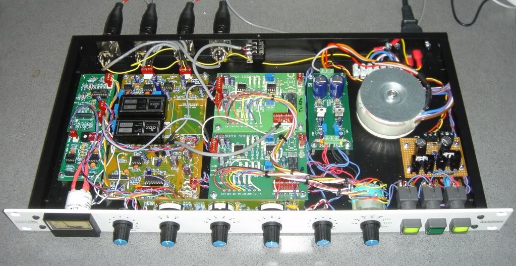
I have just finished my GSSL 'ultimate' build. Dual SSC with TL & TM plus Turbo based on 202 Black Can.
This is now a 4 mode compressor: GSSL, GSSL + SSC, Turbo, Turbo + dual SSC.
Thanks to a whole load of people:
Of course "the usual suspects."
+ Gyraf for starting all of this off
+ Parusha for the case
+ Gustav for the PCBs
+ Dafydd Roche (Expat Audio). These boards were a joy to work with.
+ MNATS for the PSU boards (left over from a 1176 build)
+ Marcfrom for convincing me to use the 202 Black Cans
I did a load of testing on looking at the various sensitivity slopes for the different VCA's, which I'd like to share with you.
I looked at 4 different methods of tuning the sensitivity and control port impedance differences.
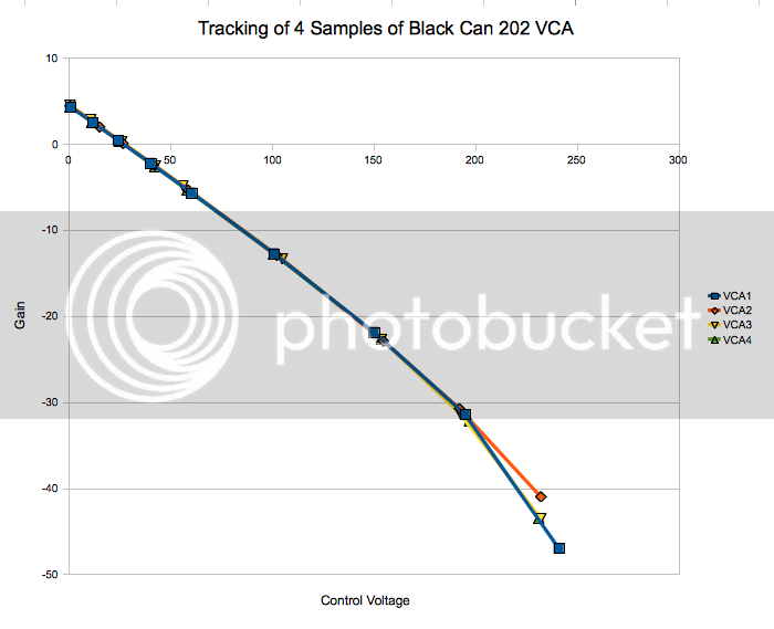
1) Checked 4 different samples of 202 Black can VCAs for manufacturing variations to see if they tracked each other.
They did very well up to pretty large compression ranges, although they were not linear at extreme GR.
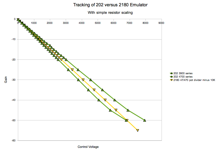
2) Checked what the 2180 Emulation Circuit did with Gssl 2180 circuit 47/470 divider 6mA/V No Turbo
With and without 10K and also with op amp scaling (5K6 feedback resistor) instead of the 47/470R potential divider.
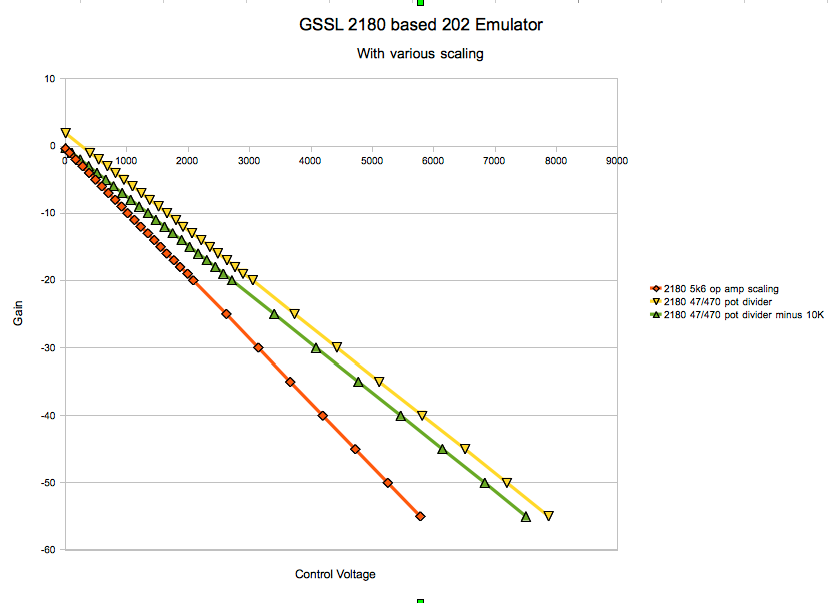
The 2180 behaved much more linearly than the older circuit, and the lines matched predictions based on the data sheet.
Interestingly enough, the potential divider is straighter than the op amp scaling. Op amp scaling also "curved the wrong way" at high GR compared to the 202.
You can also see that the 10K resistor simply offsets the curve but does not change its shape, like having a permanent make up gain setting.
Since this is a partial feed forward design, it's important that the SC vca matches the signal chain vca.
3) I looked at various combination of op amp scaling = changing the 100K TL072 feedback resistor, using a potential divider, or changing the 1K resistor to various values.
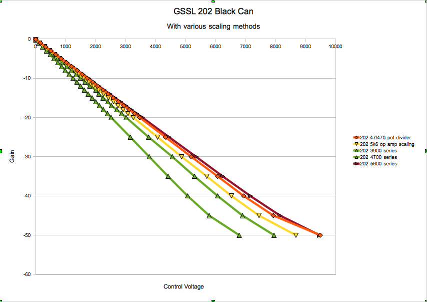
I then checked the tracking against the 2180 emulator. It was good to 40dB of GR.
Clear conclusion: simplest and best match to the 2180 emulator is to use a simple resistor change, and to add a small 2K variable trimmer in series with a fixed 3K3 resistor instead of the 1K used in the documented design for the 202X.
So what I really wanted to post was my experiences with the Black Can 202 and the mods I made:
Here they are:
Swap 6uF and0.47uF tantalum capacitor next to RELEASE switch (91K and 760K resistors are labelled incorrectly on the board!)
Remove 10K between pin 5 & 2 of all 2180 VCA's (including turbo board)
This has been pointed out by other people. The 10K sets a gain offset of 4dB at 0 CV.
I also recommend to remove it.
Remove 47 or 68 ohm from pin 4 of all 2180's (2180 is already trimmed)
Replace 15K/27K input resistor on pin 1 of Right and Left Black Can VCA's with 68K (higher input impedance of black can)
Replace 15K output resistor on pin 8 of Black Can VCA with 33k + 5K variable trimmer (to adjust to 0dB gain at 0 compression)
Most important: replace 1K resistor to CV of black can 202 with 3K3 + 2K trimmer (expect to set at about 4K) to match gain reduction with internal VCA (±138 mV/dB), because of lower input impedance and higher sensitivity of CV control port on black can 202.
Majorly butchered switching on the SSC boards, so that it is in the default mode with the relay unpowered (to avoid the relay getting magnetized) and so that one board switches the Turbo mode and the other the bypass.
turbo board
dual SSC (aligned filters separately)
VU meter board (although I wish there was more room for a VU source selector switch)
Off board PSU for the main boards.
Separate power supply for the lamps etc.
The almost finished product. (Well one of them... I built two.)
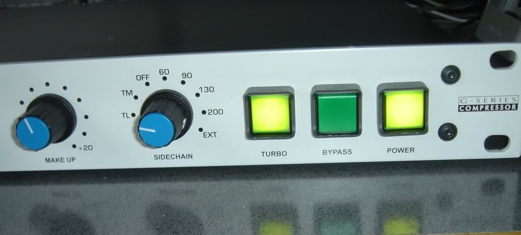
The GR, the GR meter, and the SC GR all track to within a dB over the whole range.
I might yet fiddle with the 620K make up gain resistor (currently gives 14dB max rather than 20dB) and the threshold pot resistor, so that they match the front panel scales, although it won't affect base functionality.
This is now a 4 mode compressor: GSSL, GSSL + SSC, Turbo, Turbo + dual SSC.
Thanks to a whole load of people:
Of course "the usual suspects."
+ Gyraf for starting all of this off
+ Parusha for the case
+ Gustav for the PCBs
+ Dafydd Roche (Expat Audio). These boards were a joy to work with.
+ MNATS for the PSU boards (left over from a 1176 build)
+ Marcfrom for convincing me to use the 202 Black Cans
I did a load of testing on looking at the various sensitivity slopes for the different VCA's, which I'd like to share with you.
I looked at 4 different methods of tuning the sensitivity and control port impedance differences.
1) Checked 4 different samples of 202 Black can VCAs for manufacturing variations to see if they tracked each other.
They did very well up to pretty large compression ranges, although they were not linear at extreme GR.
2) Checked what the 2180 Emulation Circuit did with Gssl 2180 circuit 47/470 divider 6mA/V No Turbo
With and without 10K and also with op amp scaling (5K6 feedback resistor) instead of the 47/470R potential divider.
The 2180 behaved much more linearly than the older circuit, and the lines matched predictions based on the data sheet.
Interestingly enough, the potential divider is straighter than the op amp scaling. Op amp scaling also "curved the wrong way" at high GR compared to the 202.
You can also see that the 10K resistor simply offsets the curve but does not change its shape, like having a permanent make up gain setting.
Since this is a partial feed forward design, it's important that the SC vca matches the signal chain vca.
3) I looked at various combination of op amp scaling = changing the 100K TL072 feedback resistor, using a potential divider, or changing the 1K resistor to various values.
I then checked the tracking against the 2180 emulator. It was good to 40dB of GR.
Clear conclusion: simplest and best match to the 2180 emulator is to use a simple resistor change, and to add a small 2K variable trimmer in series with a fixed 3K3 resistor instead of the 1K used in the documented design for the 202X.
So what I really wanted to post was my experiences with the Black Can 202 and the mods I made:
Here they are:
Swap 6uF and0.47uF tantalum capacitor next to RELEASE switch (91K and 760K resistors are labelled incorrectly on the board!)
Remove 10K between pin 5 & 2 of all 2180 VCA's (including turbo board)
This has been pointed out by other people. The 10K sets a gain offset of 4dB at 0 CV.
I also recommend to remove it.
Remove 47 or 68 ohm from pin 4 of all 2180's (2180 is already trimmed)
Replace 15K/27K input resistor on pin 1 of Right and Left Black Can VCA's with 68K (higher input impedance of black can)
Replace 15K output resistor on pin 8 of Black Can VCA with 33k + 5K variable trimmer (to adjust to 0dB gain at 0 compression)
Most important: replace 1K resistor to CV of black can 202 with 3K3 + 2K trimmer (expect to set at about 4K) to match gain reduction with internal VCA (±138 mV/dB), because of lower input impedance and higher sensitivity of CV control port on black can 202.
Majorly butchered switching on the SSC boards, so that it is in the default mode with the relay unpowered (to avoid the relay getting magnetized) and so that one board switches the Turbo mode and the other the bypass.
turbo board
dual SSC (aligned filters separately)
VU meter board (although I wish there was more room for a VU source selector switch)
Off board PSU for the main boards.
Separate power supply for the lamps etc.
The almost finished product. (Well one of them... I built two.)
The GR, the GR meter, and the SC GR all track to within a dB over the whole range.
I might yet fiddle with the 620K make up gain resistor (currently gives 14dB max rather than 20dB) and the threshold pot resistor, so that they match the front panel scales, although it won't affect base functionality.
Hi,
You mean to change the 15Kohm which is between pin 2 and pin1 of the 5532 (C Reaction resistor?) to 27Kohm?
And concerning the27Kohm input resistor, someone told me to set a 13,5Kohm resistor there (or two 27Kohm in parallel)
Is it ok?
In addition, what should I do with the resistors labelled 100R*, 47K*
Also, I did the board myself... I don't know anymore when...
Can someone tell me the mod which has been done on the PCBs versions?
Only this has to be change or is there also some condesators to change?
On the components (above) view, I see that "he" mentionned a revsion history:
Starting from 5 by the way... Considering that I don't know when I did the PCB, it would be good to know what were the REV 1... Rev4 modifications... Someone can help?
About Rev 5: So, the input must be at the GND... Why? My be it is better to connect directly the pin - of the 5532 to the GND?
About REv 7: CAP values at TL074... PAD W14= 94... Is it only a spacing modification?
About Rev 8: Only a PAD spacing mod too?
About Rev 9: Only relevent for a the THAT 2181?
Did someone did a GSSL using DBX 202C also for the enveloppe detection?
Thanks!
PK
Similar threads
- Replies
- 3
- Views
- 1K
- Replies
- 3
- Views
- 99