design ideas

GroupDIY Audio Forum

Help Support GroupDIY Audio Forum:

This site may earn a commission from merchant affiliate links, including eBay, Amazon, and others.

ioaudio

Well-known member
Joined
May 11, 2005
Messages
2,087
Reaction score
497
Location
vienna/austria
might be odd to most of all,

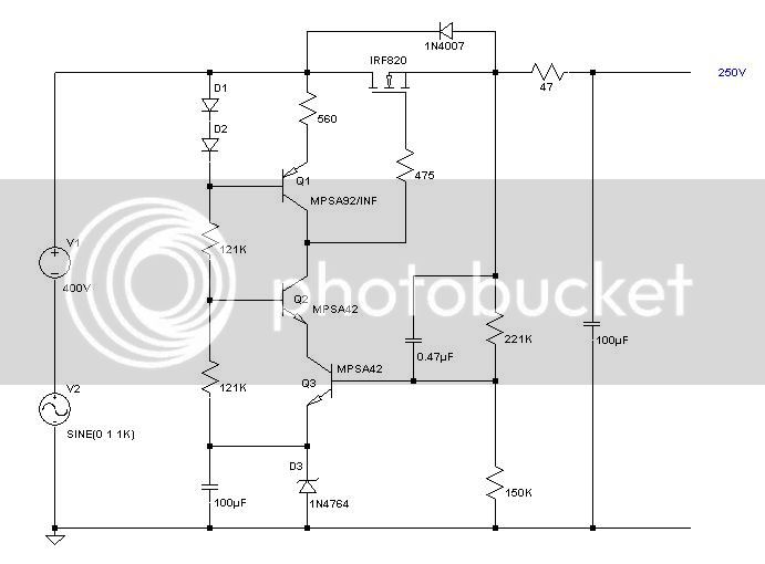
but the approach to my designs is based on which parts i find on the flea market...


iomic2.jpg


its not a finished design yet, i need to implement (global) feedback, will be the tricky part i guess-suggestions welcome.

edit: changed title to design ideas. would be nice if some of you would come up with any "homegrown" ideas, so we can mix them up :cool:
 
Normally the top of that resistor would go to a 20uF filter cap and then thru a 10k to 100k resistor to the B+ supply.

Unless I am missing some sort of cool new feedback technique.
 
Well let's see....(4) gain stages (4) coupling caps (2) transformers with the first plate resistor connected directly to the second tube's plate and you want to implement global feedback. What is it a preamp or an experiment. You even bypass the cathode of the first tube for more gain. I think you have too much of everything in your design.
 
You could wire up what you have to an experimental chassis jig and just start throwing some parts around. Often times, this is quicker than doing a theoretical analysis on the circuit. Just use a pair of clip leads to dial in your components, maybe a cut wire here, and a splice there, and when you get it where you want it, you can clean it up and rack it.

The cap on the first stage Triode is not that big a deal, try it both ways.
 
[quote author="analag"] What is it a preamp or an experiment.[/quote]

both, hopefully, as always.
my intention was to share it, before its finished. far from being finshed, though. and as far as i found out while breadboarding, yes you´re right, way too much gain.

[quote author="CJ"]You could wire up what you have to an experimental chassis jig and just start throwing some parts around.[/quote]

thats my approach. before i power up, i put the schematics in here to make sure that i wont hurt myself :musique:

hopefully you people can get some inspirations from my odd "designs" :roll:
 
you can't get hurt with that circuit, now the pwr supply, thats a different story.

you have a supply schematic or do you need one?
what kind of parts do you have on hand? Pwr transformer specs?
 
[quote author="CJ"]you can't get hurt with that circuit, now the pwr supply, thats a different story.[/quote]

i will not get hurt, i´ll take care.
i already build an external psu (~260v B+ unregulated choke, 6.5v dc heaters and 47.5v baumann phantom supply in onebox) which works quite good(as descibed in the ef86/ecc81 thread).

indeed i couldnt find a lot of ht supply schematics, would be great if you could come up with one.
 
Your schematic reminds CJ of the V76....well kinda sorta
Do you want a regulator schematic?
Regulator.jpg


I posted this one before, but here it is again. I have a few of em living in my studio.

Analag
 
Back
Top