DiY AMI U47

GroupDIY Audio Forum

Help Support GroupDIY Audio Forum:

This site may earn a commission from merchant affiliate links, including eBay, Amazon, and others.
Hey Dmp,thx for reply, so did you have that hum too? Could you improve this? Dennis from Ami checked my layout and told me that it is ok...but maybe there is a better ground layout .....would really like to sort that out..thx
 
Do you have a schematic for the AMI power supply? I would assume that would be capable of running a U47 quietly, but you never know.

You just have to do some problem solving to figure it out.  Gather more info
Swap the tube - better?
Confirm mic body grounded?
Turn of PSU - does the mic operate quietly for a few seconds?
Move mic to a different room (possibly away from a computer monitor, dimmer switch, or flourescent light)
Try a different U47 psu - better?
etc...
 
Hey DMP , only thing i could check right now : i turned the psu of and checked with an analyser : the 100hz hum disappeared but a general 50hz and harmonics ( typical ground noise ) occured immidiatly - would this be a hint for a hum from the PSU? next i will try a differnt tube...

thx D
 
Hi Guys, i wanted to report that the hum is gone -  after installing a elco 1000uF/16v parallel to R3 ( Dennis from Ami forgot that i live in Austria and eventually sent me the alternative schematics for Europe grounding scheme) the hum disapperared - maybe this helps someone in future...
 
I'm having exactly the same issue, the mic works beautifully except a small but noticeable 100Hz hum (about -78dB with 30dB preamp gain). I'm using the AMI PSU and have checked all my grounding and soldering. The mic case, body and head basket connect to binder pin 7 and the shield of the cable connects to pin 7 and the connector housing tab at both ends. The pin7 shield and pin5 0V are tied in the PSU. I'm loathe to install a cathode bypass capacitor to fix it so I'd like to exhaust all other options first. Has anyone else come across this problem and fixed it? I'm based in the UK. The power transformer failed after a short time and Dennis from AMI has been amazing at sending a replacement very quickly and answering all my questions. At first I connected the internal tube shield pin 6 to the heater 0V at pin5 but Dennis said to connect it to the anodes pins 7, 8, 9. The hum is still there. I am not detecting any ripple on the 120V or the 5V lines, although I only have a multimeter and not a scope. The mic is so beautiful and delicate, I hate taking it apart to work on it, and of course you have to replace the body and head basket every time you make a change to hear if it has worked.
 

Attachments

  • Screen Shot 2018-02-13 at 11.53.04.png
    Screen Shot 2018-02-13 at 11.53.04.png
    126.1 KB
Anyone have any thoughts about this? Is it possible that the exact routing of the 0V lines inside the mic could have an effect on hum? I currently have them on a sort of buss running from top to bottom, so C2 (underneath capsule ) - wire - EF800 pins 5 & 6 & R1 - wire - R3 & R7 - wire - C5 & C1 & BV8 transformer white - wire - binder pin 5. Would running a separate wire from heater 0V to binder pin5 to all the other 0V connections be worth trying?
 
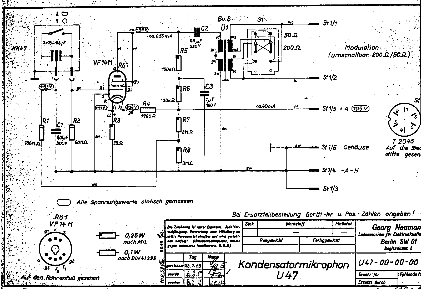
I fitted a 1000uF Cap across R3 (from grid to ground), and the 100Hz hum has gone. I think this must mean there is some ripple getting in on the heater line? In Europe with the 50Hz mains perhaps it sneaks through the filtering network more obviously than in the USA. I don’t have a schematic but by poking around in the PSU I can see that C1/R3/C2/R4/C3 form a filter network with the cutoff frequency of 7.5 ohms and 1000uF being 21.2Hz. 4700uF caps would produce a cutoff frequency of 4.52Hz, much better and lower than 21.2Hz. Is this the right thing to try or am I missing something? By what I've read of Oliver posting himself, bypassing the 27 ohm cathode resistor with a big electrolytic is less than ideal, even though we're not really in a cathode bias scenario it will still change the sound slightly (increased gain and distortion).
 
The whole point of the U47 circuit is to not have a capacitor on the cathode resistor. The tube is put into a "fixed" bias by using the heater current to develop a bias voltage across the small 29 ohm resistor. In order to do this in a mic, the heater supply must be extremely well filtered. Cutting any corners on the PSU leads to a poor mic. It is not apparent to many that the PSU of tube mic is very important to the quality of the overall mic.

If you could post a sketch of the heater filtering circuit we might be able to see if it looks sufficient.

I have built a U47 with poctop's choke PSU and it it performs great.  This is the schematic:
https://cdn.groupbuilder.com/groupdiy/u/39511/58d1402a0714e.pdf

The heater voltage comes in at 20v AC  and goes through the choke at X1 to come out at the heater voltage DC.
15R - 4.7uf - choke - 4.7uf - 15R - 10000 uf - 15R - 10000 uf - ~50R - 10000 uf ->


Wow that’s a lot of filtering, or at least a lot more than I have. What value choke is it? We’re looking at 330mA through it. That original VF14 design is such a beauty isn’t it. With a high voltage low current heater you only need one power supply rail to put all your capacitors, and because it’s high voltage you can afford more series resistance and therefore need much less expensive shunt capacitance to get your low corner frequency for good filtration.  We’re stuck with needing shedloads of capacitance because of the low voltage drop we can afford with small value resistors, and big expensive chokes to handle the higher current on our separate heater supply.
 
To be clear I haven’t got the schematic for my psu and it has a more complex circuit I described including possibly an integrated circuit, but I can only see 4x 1000uf capacitors and no inductor.
 
I never did measure it but I had what sounded like 120Hz hum on my Poctop M49 build. It turned out to be a grounding issue.

I changed my PS to mrerdat's recommended scheme in the U67 thread:
https://groupdiy.com/index.php?topic=50021.msg796487#msg796487

Basically, if you're 0V inside your mic is bonded to the shield then your 0V in the power supply should only be connected to the chassis via a switch. This is what the Neumann schematics show. Your AC ground MUST be terminated to the chassis and your multi pin shield must be terminated to chassis.

The idea is that the 0V is only connected to the chassis / shield (think of the chassis as an extension of the shield) in two places. If a ground loop happens then you can open the connection between 0V and the power supply chassis breaking the loop.
 
Hmm interesting thanks for that. The mic chassis is connected to binder connector pin7 which is the shield of the cable. 0V in the mic is connected to binder pin 5 which is connected to the chassis earth in the PSU. AC earth connects to PSU chassis by the IEC. I thought this was the cleanest way to do it, connect chassis and cable shields to 0V in only one place inside the PSU, and keep them separate until then.
 

Attachments

  • IMG_0127 small.jpeg
    IMG_0127 small.jpeg
    281.7 KB
U47 0V tied to ground inside mic:
u47.gif


I can't speak for the original U47 power supply but the M49 and U67 supplies both have the 0V only tied to the chassis via switch. Shield of course connected to chassis.
 
Having the ground scheme is important to have a quiet mic and a ground loop manifests similar to insufficient PSU filtering. But if adding a cap to the cathode resistor cuts the noise, it is probably not a ground loop?  I could be wrong. Troubleshooting issues like this is the hardest part of DIY mic builds.
 
I solved the hum problem, to cut a long story short it was insufficient filtering in the heater supply.

I replaced C1 and C2 with 4700uF 35V types, C3 and C7 with 10,000uF 25V types. I also replaced R3 and R4 with inductors; I was very happy to discover the existence of these little $2 EPCOS B82731M2351A030 double chokes, at 200mH 9ohms 350mA wired in series they are perfect for the job. This amount of extra filtering is probably overkill and it would probably be fine with just the bigger capacitors but it works beautifully :)
 
emi2345 said:
I solved the hum problem, to cut a long story short it was insufficient filtering in the heater supply.

I replaced C1 and C2 with 4700uF 35V types, C3 and C7 with 10,000uF 25V types. I also replaced R3 and R4 with inductors; I was very happy to discover the existence of these little $2 EPCOS B82731M2351A030 double chokes, at 200mH 9ohms 350mA wired in series they are perfect for the job. This amount of extra filtering is probably overkill and it would probably be fine with just the bigger capacitors but it works beautifully :)


Those chokes are a great deal! 
 
So...

I just finished what I believe to be a matched pair of these u47s with ef802 tubes, using the remote pattern switching psu. They both sound the same in all configurations, but when switching mic #2 to omni, it goes silent and audio starts to return and then a loud clipping/thumping starts cycling slowly and ramps up in speed and then stops and then the mic functions properly in omni. Any ideas what might cause this?

-Brian
 
It could be a slight short in or at the capsule.  You could sustitute a small value capacitor (60pf-100pf) capacitor for the capsule or switch capsules and see if the problem persists.
 

Latest posts

Back
Top