You are using an out of date browser. It may not display this or other websites correctly.
You should upgrade or use an alternative browser.
You should upgrade or use an alternative browser.
DIY API 1604 inspired mixer (16x8x2)
- Thread starter boji
- Start date
Help Support GroupDIY Audio Forum:
This site may earn a commission from merchant affiliate
links, including eBay, Amazon, and others.
boji
Well-known member
Beginning to stuff mute/solo pcb's. Super fast turnaround from DirtyPCBs (~12days)!
Once code plays nice with four of em', next step is to stack and rack near the PSU and send I/O into fader wells.
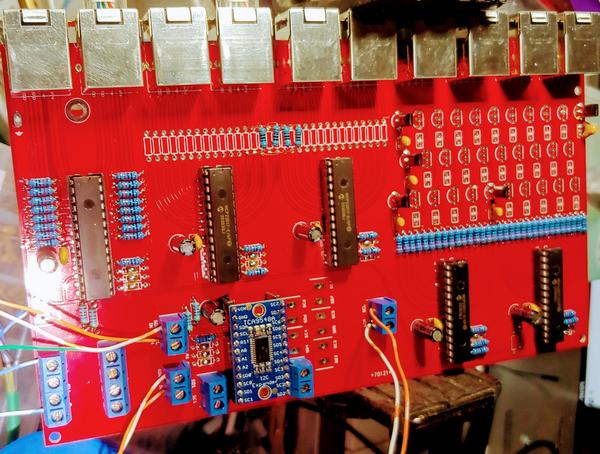
Edit: Thanks again to Squarewave for advice on bus communication protocols (SPI/I2C).
Once code plays nice with four of em', next step is to stack and rack near the PSU and send I/O into fader wells.

Edit: Thanks again to Squarewave for advice on bus communication protocols (SPI/I2C).
Fsharpminor
Active member
- Joined
- May 4, 2015
- Messages
- 41
Amazing to see this progress, thanks for the documentation!
JW
Well-known member
Are there going to be kits?
boji
Well-known member
You're welcome F#, and Faze no, sir, I am not worthy of yall!
JW: I'll have some extras left over if you want to play around, but the layout of the boards are fairly application specific (in hindsight, outrigging logic was a noob move). Each pcb does 16 buttons with illum and cv pulldown and offers expansion over 8ch mux.
Update:
Ready to be stuffed into console! Have to build an access door for it this weekend, as it is to be mounted behind the patchbays.
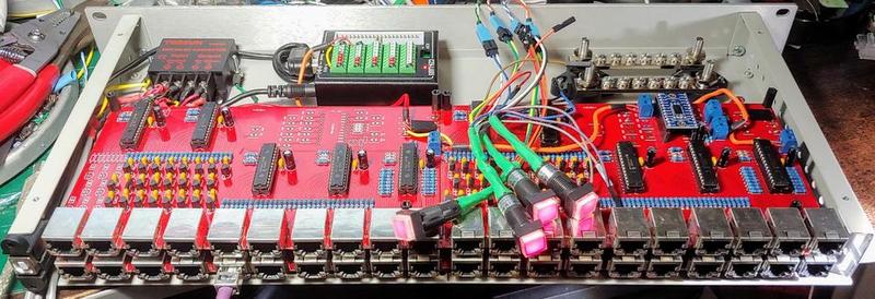
16 down, 24 to go...
JW: I'll have some extras left over if you want to play around, but the layout of the boards are fairly application specific (in hindsight, outrigging logic was a noob move). Each pcb does 16 buttons with illum and cv pulldown and offers expansion over 8ch mux.
Update:
Ready to be stuffed into console! Have to build an access door for it this weekend, as it is to be mounted behind the patchbays.

16 down, 24 to go...

boji
Well-known member
Thanks Perm0!
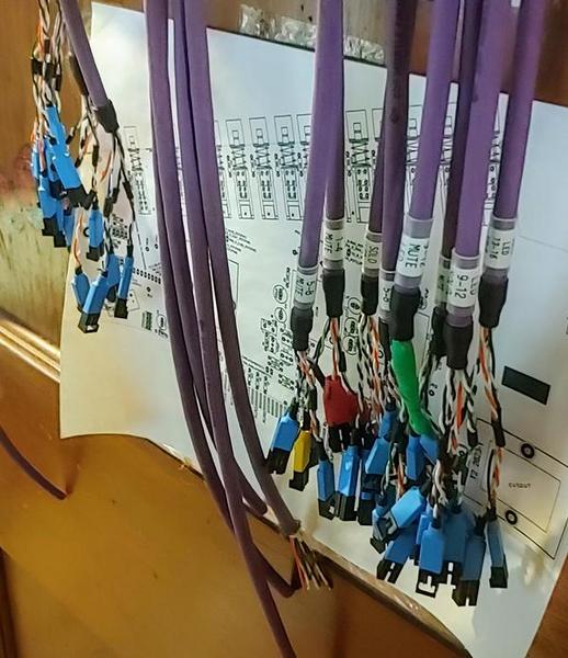
...here really comes the madness: Time to permanently install i/o conn.
...here really comes the madness: Time to permanently install i/o conn.

I'm a wiring tech, OBV's, broadcast installations etc...
I see no problem there, I see a well prepared job and as long as you did not plan to make a rushjob out of this, it will be great.
Vey inspirational to see someone taking on a project like this, knowing it will be insanity, but does it anyway as it's the most sensible thing to do.
As it will be, when it's finnished, it will all make perfect sense 8)
boji
Well-known member
Been awhile since I checked in, so here's an overdue update as I round third base:
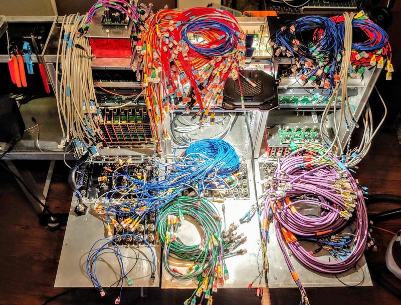
All the trunk wiring is done. So many bugs had me pulling my hair out. Some had to do with breaks in cable due to stress, most issues were a result of over-crimping, discoverable only with continuity tests--a real headache. Surprisingly, no issues were had with 100+ RJ45 jacks.
Group bucket:
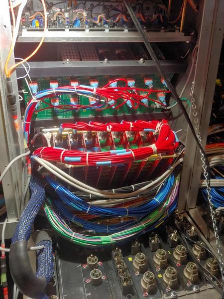
Channel buckets:
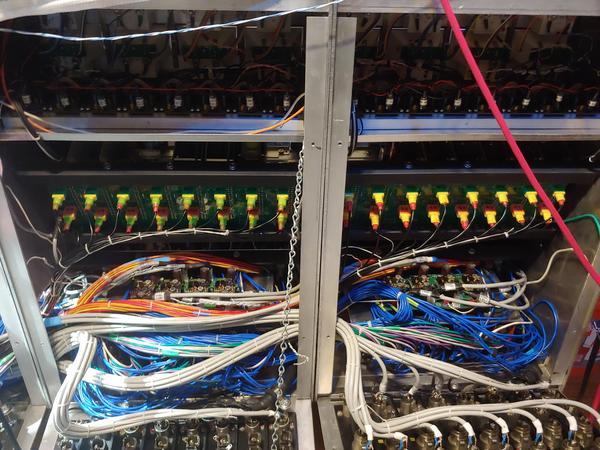
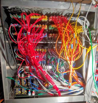
80% of the patch panel is sorted out and complete. Will tidy up once auxes are added:
Main ACA's loosely installed, all program assignments successfully pass audio to stereo bus. Noise floor is at an ok -72dB with the hopes it will improve once a dedicated earth line is run.
Cv/relay logic is fully working: group sends, pre/post 500 inserts and swaps. VU buffers and nanopixel led code is working as intended.
Next up is to run shielded control lines under the faders and connect to mute/solo buttons and relays, then rack up the Grace M905, add I/O connections to patch, and install the modded control panel. I'll post picts once installed.
Should be able to start passing some mixes in a few weeks which of course it a huge milestone, one of the last!
More later. Thanks again for everyone's help. In all seriousness-- couldn't have built this thing without you!
All the trunk wiring is done. So many bugs had me pulling my hair out. Some had to do with breaks in cable due to stress, most issues were a result of over-crimping, discoverable only with continuity tests--a real headache. Surprisingly, no issues were had with 100+ RJ45 jacks.
Group bucket:

Channel buckets:

80% of the patch panel is sorted out and complete. Will tidy up once auxes are added:

Main ACA's loosely installed, all program assignments successfully pass audio to stereo bus. Noise floor is at an ok -72dB with the hopes it will improve once a dedicated earth line is run.
Cv/relay logic is fully working: group sends, pre/post 500 inserts and swaps. VU buffers and nanopixel led code is working as intended.
Next up is to run shielded control lines under the faders and connect to mute/solo buttons and relays, then rack up the Grace M905, add I/O connections to patch, and install the modded control panel. I'll post picts once installed.
Should be able to start passing some mixes in a few weeks which of course it a huge milestone, one of the last!
More later. Thanks again for everyone's help. In all seriousness-- couldn't have built this thing without you!
scott2000
Well-known member
Massive props!
rp
Well-known member
+1 on the nice looms! Those must be pretty satisfying to tie up.
I'm in awe of this whole project. Best of luck with the continued assembly!
I'm in awe of this whole project. Best of luck with the continued assembly!
ruffrecords
Well-known member
I think you now officially officially lost your mixer builder's cherry.boji said:Been awhile since I checked in, so here's an overdue update as I round third base:
All the trunk wiring is done. So many bugs had me pulling my hair out. Some had to do with breaks in cable due to stress, most issues were a result of over-crimping, discoverable only with continuity tests--a real headache. Surprisingly, no issues were had with 100+ RJ45 jacks.
Welcome to the club.
Cheers
Ian
JW
Well-known member
A couple questions about the line input circuit.
For the protection diodes on the input, are 1N4004 okay?
For the filter caps on the main bi polar rails (next to each opamp) how high is too high? CAPI usually uses 47uF or 33uF here I believe, with API using slightly lower originally. Is 220uF too high? I ask because I have a lot of them in the Elna Silmic variety. Is there a danger of the supply becoming too 'stiff' or something? (I don't know what that means but I've heard guitar amp builders describe amps like this in regards to too much filter capacitance. . . )
Last question, I was doing CMRR adjustment by sending 100Hz to both + and - ins on the first opamp and measuring with a DMM on the output of the first opamp. I seem to be getting 1.9mV to 2.0mV AC now matter how far I turn the CMRR trimmer or how much signal I'm sending in. I'm wondering if this is normal and what I'm not seeing is the succeeding decimals that my DMM doesn't show? Like, I need a finer measurement tool on the output? Or should I be seeing some more dramatic changes?
Ricardus
WILL SOLDER FOR FOOD
Can I order one in Fuchsia?
boji
Well-known member
Thanks guys for the love, it is fuel to get towards mixing something.
Ricardus, you can have any color you want as long as it's vantablack and used with the lights off.
JW, I'll send you a PM. Short answer on cmrr-- some dc offset is normal for a vintage 2520 circuit, and is why there's a 470uF cap between opa output and primary of output tx.
Ricardus, you can have any color you want as long as it's vantablack and used with the lights off.
JW, I'll send you a PM. Short answer on cmrr-- some dc offset is normal for a vintage 2520 circuit, and is why there's a 470uF cap between opa output and primary of output tx.
Last edited:
boji
Well-known member
Basic mute / solo buttons installed and working:
Still need to code for a monitor controller switching so that AFL/PFL bus replaces pgm mix when any solo button is pressed, and reverts back when no solo buttons are active. This will require tapping into the buttons on the Grace controller- Will begin a breadboard test this weekend.
Edit: forgot to mention a friend brought up his love of SIF, and got me thinking...all that's needed would be to mult out an attenuated pgm mix sent into solo bus monitor, so thinking of including this as well.
Last edited:
Similar threads
- Replies
- 2
- Views
- 785
- Replies
- 14
- Views
- 3K
Latest posts
-
-
-
LDC and SDC (nominally cardioid) polar patterns varying by frequency
- Latest: Det van Rijn
-
-
-
-
-


