DIY Drip UE-100 eq Klein & Hummel

GroupDIY Audio Forum

Help Support GroupDIY Audio Forum:

This site may earn a commission from merchant affiliate links, including eBay, Amazon, and others.

fobee

Active member
Joined
Nov 8, 2013
Messages
44
Hey Gang,
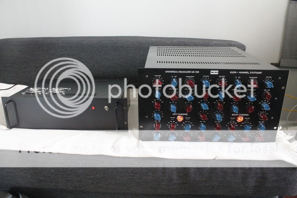
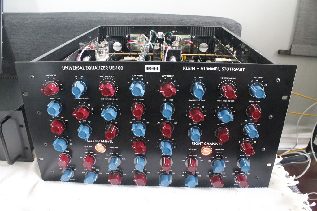
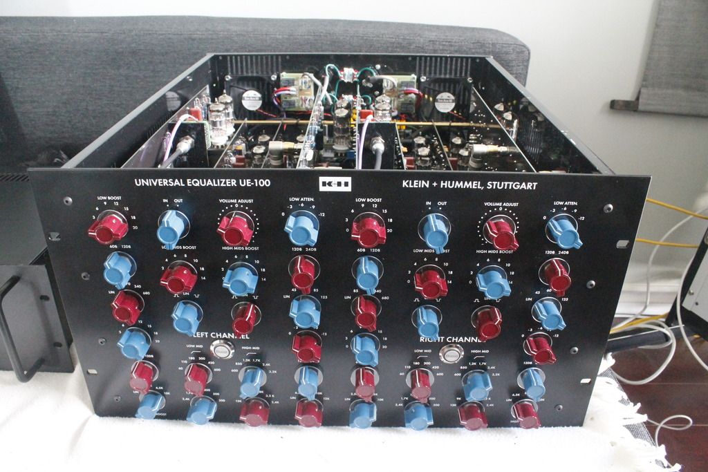
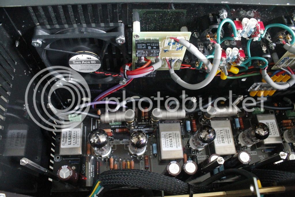
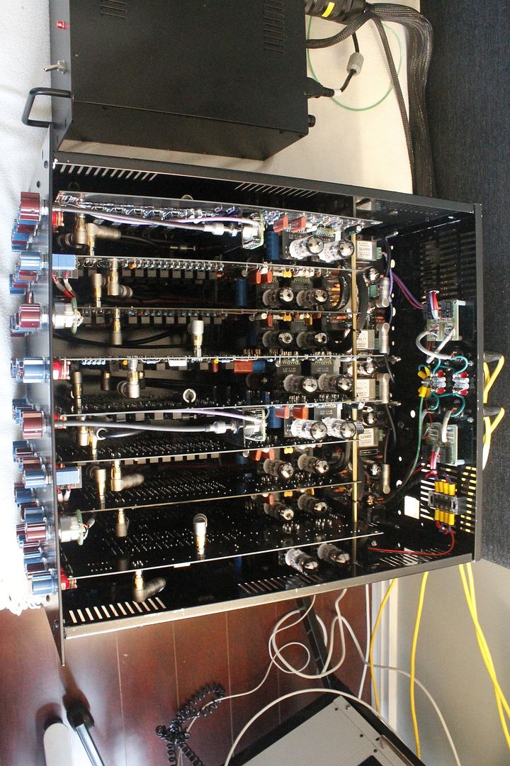
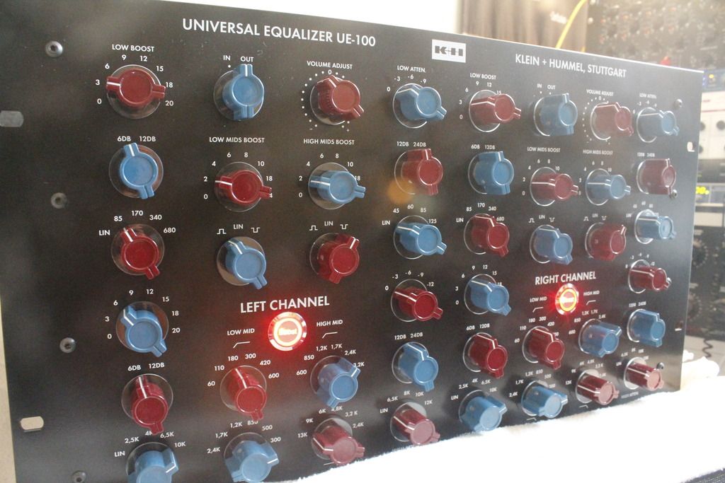
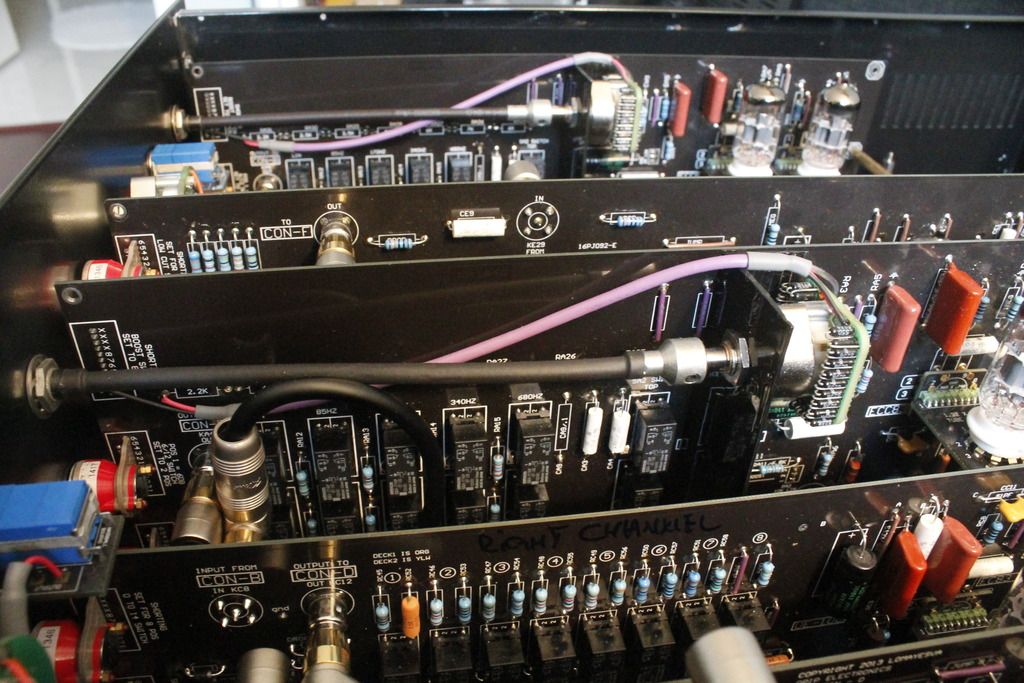
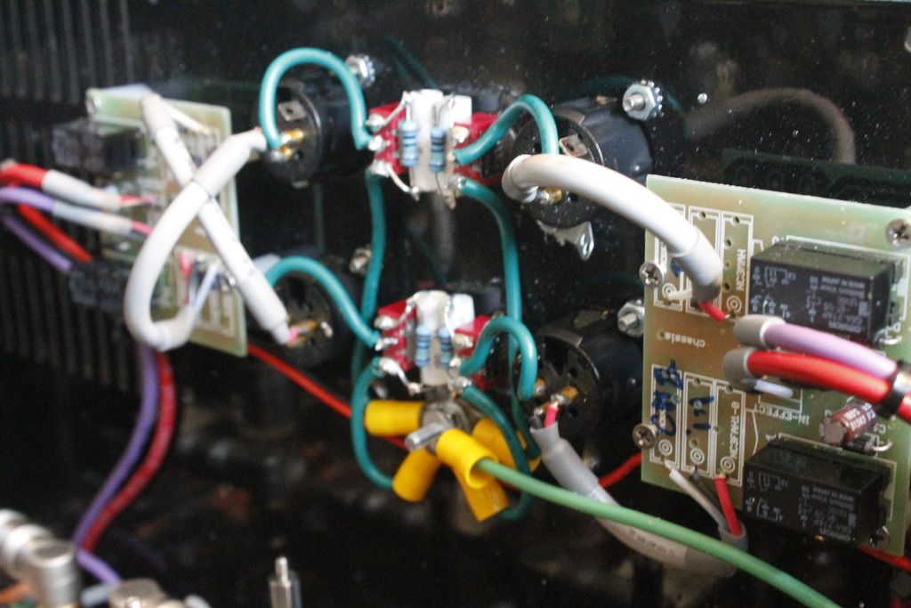
I finally finished this monster. Lots of mods = lots of money. But in the end its a very smooth and sweet eq.
Runs like a Swiss Watch! The Bass on this thing is MASSIVE! This is truly the Fairchild 670 of Eq's

Oh, I almost forgot to thank Greg @ Drip and the Crew for pulling this amazing project for us!

Cheers
George


Hopefully, I will be receiving my Case tomorrow, so then I will power up.

Three small questions regarding your build:

-Using the Sowter Mains Trafo, you incorporated the bypolar patch described in the manual, right?
-You didn´t use any chokes, correct?
-Did you calibrate the trimmers for the 6db etc. yet?

When everything works out, my unit will be fully finished in the next days!
 
DonnieDarko said:
Hopefully, I will be receiving my Case tomorrow, so then I will power up.

Three small questions regarding your build:

-Using the Sowter Mains Trafo, you incorporated the bypolar patch described in the manual, right?
-You didn´t use any chokes, correct?
-Did you calibrate the trimmers for the 6db etc. yet?

When everything works out, my unit will be fully finished in the next days!

Nice! I'm waiting for my case too. I suspect I will have to modify it to install Fans on the PS.

Yes, I've used the Sowter Mains with the bipolar patch for the +100V and - 100V
I did not use the chokes, I don't think I will in the future. The PS seems to be pretty clean although I still have to use a scope to find out.

Funny enough I have not touched the trimmers yet. Obviously I will adjust them before the final build bit I've gotta tell you that the channels were bang on! I have not touch them and still the channels were calibrated to my ears. Those trimmers are very fine adjustments and again, I will have to use and oscilloscope for that.

Good luck with your build and post some pics once it's ready!
Cheers
 
Looks very nice! I think I have to do something similar if I want to get my stuff running in the next 2 months…

What kind of connector do you use there? And where is the small PSU controlling the fan voltage (i think) come from? Very clean wiring mate!
 
DonnieDarko said:
Looks very nice! I think I have to do something similar if I want to get my stuff running in the next 2 months…

What kind of connector do you use there? And where is the small PSU controlling the fan voltage (i think) come from? Very clean wiring mate!

Thanks Donnie. I've purchased the Variable Power Supply from ebay http://www.ebay.com/itm/151440263473?_trksid=p2059210.m2749.l2649&ssPageName=STRK%3AMEBIDX%3AIT

I've used 19 Pin Socapex Style Female In-Line Connector with 19 Pin Socapex Style Male Panel Mount Connector purchased on ebay as well. http://www.ebay.com/itm/170794349832?_trksid=p2059210.m2749.l2649&ssPageName=STRK%3AMEBIDX%3AIT
 
Nice and clean - but we should never use male connectors for voltage ...

I agree - switching to a female panel mount would be much safer - with tube circuits you have deadly voltages exposed with those male pins. It's not worth the risk.

Fantastic build! .
 
dmp said:
Nice and clean - but we should never use male connectors for voltage ...

I agree - switching to a female panel mount would be much safer - with tube circuits you have deadly voltages exposed with those male pins. It's not worth the risk.

Fantastic build! .

I could do that, no problem. The Power supply has some draining resistors though, and once powered down they will drain the capacitors pretty fast.
 
I could do that, no problem. The Power supply has some draining resistors though, and once powered down they will drain the capacitors pretty fast.

Still - you only need to imagine one scenario where it gets unplugged with the psu powered up (say the power cable is wrapped around a table leg) and then you have deadly voltages exposed. Not worth the risk, IMO.

Also, IMO, nothing says unprofessional & amateur build more than a safety violation like that - and it takes the whole build down to the lowest level, even though everything else is impeccable.  (no offense meant)
 
dmp said:
I could do that, no problem. The Power supply has some draining resistors though, and once powered down they will drain the capacitors pretty fast.

Still - you only need to imagine one scenario where it gets unplugged with the psu powered up (say the power cable is wrapped around a table leg) and then you have deadly voltages exposed. Not worth the risk, IMO.

Also, IMO, nothing says unprofessional & amateur build more than a safety violation like that - and it takes the whole build down to the lowest level, even though everything else is impeccable.  (no offense meant)

No worries, I will change it!  :D
 
Whoah, these Connectors are REALLY expensive.

In europe, the set for one cable will be around 350 $. Not bad!
 
DonnieDarko said:
Whoah, these Connectors are REALLY expensive.

In europe, the set for one cable will be around 350 $. Not bad!

Hi Donnie,
They're ok. I'm making my own cable though.
 
Hi Gang,
I've got bored again waiting for that freaking case and I started to hack the PCB. I've removed all the resistors for the HIGH and LOW boosts from the Baustein A and B and I mounted some 47 position Goldpoint Attenuators that I've build myself with IRC RC55 -  523 ohms. This way I will have steps in roughly 0.5 db in boosts (more or less) per position. Not Bad at all!!! This will give me about 24.05 Kohms in the chain, less than 31.2K specified in the manual , but hey: Who the hell wants +20dB of boosts on this monster? Anyways, I thought I'll post some pics for the nerds who want to do the same. Trust me, you'll probably want to have this mod on your monster sooner or later.


Hey fobee,

first of all, merry xmas to you and everybody else round here!

Finally, the improved case arrived today for my unit.

I put everything together and stumbled upon some lasst issues that you might help me out with:

The 6 green secondary cables from the sowter feed the Chan 1 Heat, Chan 2 Heat and Amp Heat.

So the 18V @ 2A for the Relays need to be fed from a second transformer? Do you have a recommendation?

Both of the orange wires go to 250 VAC, both of the pink wires go to the 100VAC tab, the grey will be isolated?

I guess you used the small PSU here:

http://www.ebay.com/itm/151440263473?_trksid=p2059210.m2749.l2649&ssPageName=STRK%3AMEBIDX%3AIT

For getting the fans to the desired speed?

Thanks man!
 
Hi Donnie
I used a Hammond 167s10 for the fans and the relays
http://ca.mouser.com/ProductDetail/Hammond-Manufacturing/167S10/?qs=yc9RBI4tIAIpKlejSqTO3g%3D%3D

You have to find one with the 220V on the primary though if you're in Europe.

The grey wire will go at the high voltage star ground .

If you take a closer look at the power supply feat in the pictures above you'll notice that i split the secondary of that 167S10: one for the 18V relays and the other for the Fans PSU.

Happy Holidays and don't forget to post some pictures with your build. I will be going on Vacation for the next 2 weeks and maybe I'll get my case in the meantime so I can finally finish this project. It's been more than 15 months since I've placed an order for those bloody PCBs! LoL
 
Back
Top