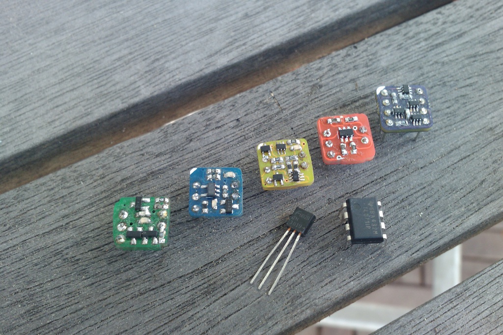
I'm not sure, but I don't think I posted about these here on the forum. All single opamps, except the last purple one which is a dual, one amp on each pcb side.

The green one uses a dual JFET for the differential input, which went obsolete between the time I designed this a couple years ago and started building a couple months ago. It's also a very basic and simplified circuit because it used SOT23 transistors, which take up too much space to allow more advanced circuit techniques. The blue one uses a lownoise dual JFET from Toshiba and the rest is
these mini duals, that allow a much higher parts density. The circuit is a simple one-stage folded cascode. The yellow one uses pnp BJT inputs with a standard two-stage topology employing more advanced elements like emitter current source, active current mirror load etc. The performance is actually good enough to use it in cleaner soundpaths (HIFI, recording, ...) as well. It consists of 10 transistors and 13 passives. The red one is all FETs and a major PITA to build. Took me two hours of matching transistors and it still didn't really go where I wanted it to. I only built one :
")
. The purple one as I already said is a dual opamp. The circuit is similar to the simpler single green one, but because of the smaller packages used I was able to fit one on each side of the pcb.
Passive parts for all of these are 0603, so still ok to handle. All you need is a fine solder tip, tweezers, fine solder and flux for soldering the little 6-pin packages. The difficulty in building these isn't the size of the parts, but the closeness to each other. Soldering one resistor can reflow another one because of the overall low thermal mass of the parts and the pcb. You have to start in the middle and work your way to the outside. While there are easier things to build it could be a nice project for people who don't have much experience with soldering SMD. Parts cost per opamp is around 1,50€, so not too much of an investment.
The intended application was for guitar effects originally, where different topologies and nonlinearities could possibly be interesting in distortion circuits. I designed all of these before I ever built the first one, and the evolution in complexity and performance is clearly visible. It's an interesting challenge to squeeze out as much performance as possible out of 1cm² of pcb real estate. I've considered redoing the layouts of the better singles to sandwich to for a dual, but so far it stayed low on my priority list.