DIY PSU for Altec 150A (M11) Coke Bottle.

GroupDIY Audio Forum

Help Support GroupDIY Audio Forum:

This site may earn a commission from merchant affiliate links, including eBay, Amazon, and others.

thecr4ne

Well-known member
Joined
Aug 26, 2016
Messages
239
Location
California
I recently got a pair of Altec 150A Coke Bottles with 21B capsules, but no power supplies. Given the prices and rarity, and what I have on hand, I think I'm better off just building my own PSU. I consider myself a novice at best, so I'd appreciate any feedback on my design logic.

Fair warning. Lots of images here interspersed with text.

I'm considering building a single PSU for both mics, like this one (currently for sale on reverb for more than I can afford) credited as build by Greg Norman of Electrical Audio.

bdgpbwli6akblygeef86.jpg


I've never really designed or re-designed a PSU before, so I'm planning on mostly sticking to the original schematic for the P518A/P519A, but with separate audio sections for each mic.

1700169604025.png


I can't find any useful info on the original TP-608-A power transformer. I know I need something that can put out 300V once rectified/filtered, plus filament with enough current to power 2 6au6 tubes.

6au6.png


I've got a Hammond 269EX on hand that I think will do the job, but I'd appreciate if anyone with more knowledge can confirm.

269EX.png


On the audio side of things, I was actually able to find some info on the original TBB-103 Output transformers.

tbb-103.png

tbb-103_.png


They're not easy to come by though, and I'm trying to keep costs down. That said I have a few (also expensive and hard to come by) 4665 transformers from my Altec 525A Lipstick mic PSUs.

4665.png


Specs seem functionally comparable. The 4665's Octal socket form factor makes it favorable in that I can use it for different applications with no soldering required.

Beyond that I can get my hands on the rest. I really just need to make sure I don't do anything stupid that could destroy the mics or output transformers. In the coming days I may try my hand at adding onto the schematic what I think makes sense, but I'm guessing I won't get it right on the first shot so any help is appreciated.


*NOTE*
I originally posted about whether the coke bottle would work with the lipstick PSU. Instead of creating a new thread, I just hijacked my own.
Original Post Below:

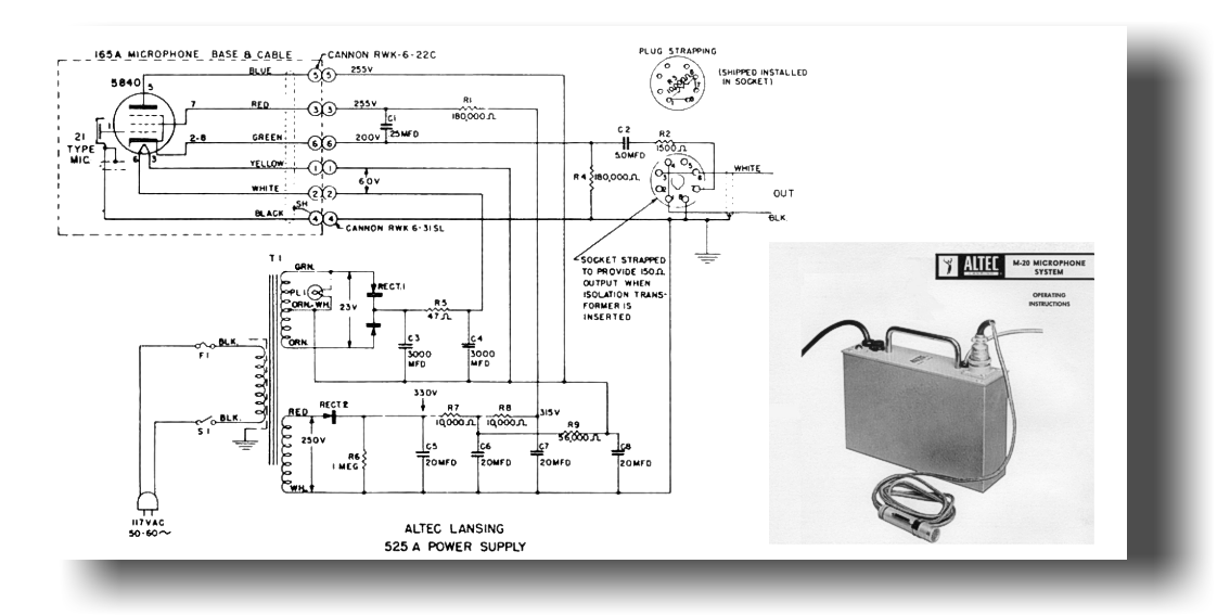
I've got some healthy recapped Altec 525A's with 4665 OTs, and recently got a Coke Bottle without it's power supply. I'm looking at the schematics and trying to see if I can use the Coke Bottle with the 525A.


Plate Voltage is 6% higher on the 518A coke bottle PSU (270V vs 255V)
Grid Voltage is 4% higher (265V vs 255V)
Cathode and heater voltages are the same.

The difference I do see is how the control and suppression grids, and backplates are wired.

Can anyone explain what's going on there and if there's any other considerations I should be aware of?
(Obviously a cable would need to be made, which is no issue)

1e05365eba86ac19dde7d50152010d46.png


518A.png

coke bottle.png
 

Attachments

  • 4665.png
    4665.png
    148.6 KB · Views: 0
Last edited:
Okay, where do we start? The task is simple, you need a suitable power supply unit plus the audio parts. This can be built originally, i.e. exactly two independent circuits like drawn in the schematic in one chassis.

Another possibility would be to realize this project a little more efficiently, which means you look at which parts you can use for both PSUs to save a few dollars. The transformer would be a good example.

You could take this step even further by modifying the original schematic. A regulated power supply for the heater would be a possibility.

This could lead to a common power supply for both microphones, you would then have to decouple the respective voltages from each other, as you do with stereo devices, to prevent crosstalk.

So there are many ways to solve this task. What do you have in mind? Original as possible or just full function?

BTW, tube power supplies are not without danger and should only be build by qualified technicans!

Thanks for the posted info, very interesting!

PS: your Hammond transformer is huge! You don't need that much current capacity...
 
Last edited:
Okay, where do we start? The task is simple, you need a suitable power supply unit plus the audio parts. This can be built originally, i.e. exactly two independent circuits like drawn in the schematic in one chassis.

Another possibility would be to realize this project a little more efficiently, which means you look at which parts you can use for both PSUs to save a few dollars. The transformer would be a good example.

You could take this step even further by modifying the original schematic. A regulated power supply for the heater would be a possibility.

This could lead to a common power supply for both microphones, you would then have to decouple the respective voltages from each other, as you do with stereo devices, to prevent crosstalk.

So there are many ways to solve this task. What do you have in mind? Original as possible or just full function?

BTW, tube power supplies are not without danger and should only be build by qualified technicans!

Thanks for the posted info, very interesting!

PS: your Hammond transformer is huge! You don't need that much current capacity.

I don't need it to be as original as possible.

Efficiency is ideal.

I don't need to go as far as regulated PSU, the original wasn't and works well enough for folks, but I'm not entirely opposed to it.

Safety practices I'm good with, and I know better than to be complacent and let my guard down. I've got practice recapping and testing tube guitar amps and the lipstick mic PSUs, among other things. It's the circuit design where I struggle.

For example, decoupling the voltages for the two channels as you mentioned to prevent crosstalk. Not a technique I'm familiar with offhand.

I'm trying to be better about gathering and posting relevant documentation. Everything is so scattered and I get frustrated hunting for docs that get referenced but not provided. Trying to make things easier for the next guy if I can.

I'll look into a smaller power transformer, but for now, since it's here, this will be a stand-in as long as it doesn't cause any problems beyond being overly capable.
 
I don't need it to be as original as possible
Okay, that has some advantages.
I don't need to go as far as regulated PSU, the original wasn't and works well enough for folks, but I'm not entirely opposed to it.
The problem with unregulated power supplies is the moment when one mic is no longer connected. Everything changes, you are forced to set everything up independently from each other.
Safety practices I'm good with, and I know better than to be complacent and let my guard down. I've got practice recapping and testing tube guitar amps and the lipstick mic PSUs, among other things.
(y)
I'm trying to be better about gathering and posting relevant documentation. Everything is so scattered and I get frustrated hunting for docs that get referenced but not provided. Trying to make things easier for the next guy if I can.
(y)(y)
I'll look into a smaller power transformer, but for now, since it's here, this will be a stand-in as long as it doesn't cause any problems beyond being overly capable.
The Hammond transformer will not work with the original schematic. The CRC filter with R11 needs a much higher secondary AC voltage for the heater!
 
It's quite late here, but I could sketch out a proposal for a solution tomorrow.

Overall an interesting project with a clever audio circuit. CF pentode amp in action! You rarely see that in a microphone.
 
The Royer project is a nearly identical 5840 cathode follower design, but uses a simpler, more common transformer for the PSU.
https://tapeop.com/tutorials/34/david-royer/
FWIW, for my Oktava MK-012 6205 (same as 5840) cathode follower mods, I used two common 12.6v transformers with their secondaries connected together to provide the low voltage for the regulated heaters, and about 90v B+ from the primary of the second trafo (from the seemingly long-lost Royer 'Country Boy's Capacitor Microphone' article (Glass Audio Vol 8 No.1) https://www.jensen-transformers.com/wp-content/uploads/2014/08/as076.pdf). But it seems the Altecs require much higher polarization voltage than the Oktavas, which don't like much above 40-45v.

Royer found that with the right cathode resistor, the 5840 is quite happy at much lower B+ than the Altecs used.

Using the omni or hypercardioid capsules, two of my best sounding mics.
 
Last edited:
The Royer project is a nearly identical 5840 cathode follower design, but uses a simpler, more common transformer for the PSU.
https://tapeop.com/tutorials/34/david-royer/
FWIW, for my Oktava MK-012 6205 (same as 5840) cathode follower mods, I used two common 12.6v transformers with their secondaries connected together to provide the low voltage for the regulated heaters, and about 90v B+ from the primary of the second trafo (from the seemingly long-lost Royer 'Country Boy's Capacitor Microphone' article (Glass Audio Vol 8 No.1) https://www.jensen-transformers.com/wp-content/uploads/2014/08/as076.pdf). But it seems the Altecs require much higher polarization voltage than the Oktavas, which don't like much above 40-45v.

Royer found that with the right cathode resistor, the 5840 is quite happy at much lower B+ than the Altecs used.

Using the omni or hypercardioid capsules, two of my best sounding mics.

Interesting. The Altec 21 series omni capsules want +200V polarization voltage, so yeah, that's the thing there. On the other hand the 29 series cardioid capsules only need +60V, and I'm considering adding the option to switch down to try the 29A with the 150A. Haven't found any info on anyone doin that.

As for the royer/country boy mics. I think I'll give that a whirl as another project. I bought a box of NOS JAN 5840W's so I'm overstocked on those and glad to have more uses for them than just the Lipstick mics.
 
I had some time today to take a closer look at the circuit during a visit to the doctor.

As I said, very interesting, some unusual solutions are used. It's true that David Royer also likes to use cathode followers as impedance converters, I think he also knew these microphones when he started.

But the difference is that Altec actually uses a pentode as a pentode and not as a triode. I've never seen that before. The polarisation voltage of the capsule is really high, it sits on the potential between R1 and R5 on the cathode side of the 6AU6.

The rumple filter is also a remarkable solution, simple but effective.

Back to the actual question, I've played through various scenarios, you can really solve this in very different ways.

I take the existing Hammond transformer as a starting point for further considerations, so the original PSU concept is ruled out.

My suggestion would be to use my tried and tested voltage doubler PSU as a basis for this. The heating winding provides enough current, that would work.

soderstrom_tube_PSU_with_voltage_doubler_heater.png
soderstrom_tube_PSU_with_voltage_doubler_heater_render.png
more info here


I thought for a while about realising the whole thing with a central PSU for both microphones. It would work, but the potential savings are small, so I would simply install two of my boards, which would be the simplest solution from my point of view.

It still needs a few minor changes, if the TO wants to go this way, I can change it so that everything fits. I hope cr4ne can etch circuit boards or knows someone who can.

One board is 80x100cm, two of them fit exactly on a 160x100 Euro board.

You would have to make a few changes to the original circuit diagram, the series resistors in the B+ power supply have to be increased, which means more ripple filtering, the regulated heater voltage is certainly not a disadvantage either.

That would be my suggestion, of course you can do it differently...
 
Last edited:
@rock soderstrom That's amazing!

So my understanding is, The Hammond pwr transformer, paralleled into two of your boards, with the adjustments you mention, each would then output +300V B+ and regulated +6.3V filament yes?

Then would the rest of the schematic post B+ just be recreated more or less according to the original schematic?

I can get boards made. If I have to order them from somewhere I'm good with that.
 
So my understanding is, The Hammond pwr transformer, paralleled into two of your boards, with the adjustments you mention, each would then output +300V B+ and regulated +6.3V filament yes?

Then would the rest of the schematic post B+ just be recreated more or less according to the original schematic?
Exactly, I initially intended to integrate all parts of the B+ power supply on my PCB in order to supply the anode and G2 with the corresponding voltages. (R7/C6 and R8/C6*) but you can also leave everything as it is and integrate the components mentioned on the audio PCB yet to be created.

Then my PCBs would supply the basic B+ of 300V, corresponding to node R15/C7* in the original circuit diagram and the regulated filament voltages, which are adjustable as required.

One challenge is the 385VAC supplied by the transformer, together with the bridge rectifier on my PCB the raw DC voltage after rectification gets really high. If you use the center tab and only fit two diodes, what is the resulting voltage? I'm not that familiar with those centertab transformers, I actually always use ones without a centertab. Can someone more experienced say something about this?
 
Thanks @rock soderstrom
I think it would be great if the other Anode and G2 voltages are integrated into the board as well, that way the power is all together.

If this particular power transformer is that much of a headache, I'm good if we spec something with more intent than just "I happen to have this one". I welcome suggestions.

EDIT: Adding here that I'm open to just doing two completely separate PSU's at this point. If we're spec'ing a new power transformer, no reason to restrict it to a single transformer for both mics.
 
Last edited:
Minor tangent to show off the mics themselves. The second arrived Friday. Both in great shape, with original cases and 21B capsules (i also have a pair each of 21D, 21-BR-150, and 21-BR-180 capsules)
PXL_20231118_011812074.PORTRAIT.jpg
 
I think it would be great if the other Anode and G2 voltages are integrated into the board as well, that way the power is all together.
I don't have any more free space on the board, I would have to make it bigger and I don't think that's really necessary as you can do the rest ripple filtering locally, on the audio board.
EDIT: Adding here that I'm open to just doing two completely separate PSU's at this point. If we're spec'ing a new power transformer, no reason to restrict it to a single transformer for both mics
I think one transformer would be sufficient, the disadvantages would be small from my point of view, compared to two separate transformers.
I think you can do it either way.
Minor tangent to show off the mics themselves.
Beautiful!
 
I don't have any more free space on the board, I would have to make it bigger and I don't think that's really necessary as you can do the rest ripple filtering locally, on the audio board.
Ok I misunderstood about the board space. Anode and G2 voltages will go on the audio board.

I think one transformer would be sufficient, the disadvantages would be small from my point of view, compared to two separate transformers.
I think you can do it either way.
I meant one transformer for each power board to do 2 separate builds instead of one combined PSU for both mics. Individual PSUs would allow for more flexibility with Mic placement and whatnot. I'm not really committed either way. I was just suggesting going with a different power transformer as a way to get away from the excessively high voltage off the 380V secondary of the hammond, and even to get a higher filament secondary if that makes more sense than the voltage doubler.

Are you up for laying out the audio board to go along with this as well?
 
Are you up for laying out the audio board to go along with this as well?
I hadn't planned it because I don't have any of these microphones. I just wanted to help you with the PSU with my suggestion.

Gift me a suitable microphone and I'll build the right PCB for it. LOL 😅
 
if only I had some to gift, ha.

I hadn't planned it because I don't have any of these microphones. I just wanted to help you with the PSU with my suggestion.

Gift me a suitable microphone and I'll build the right PCB for it. LOL 😅

could you share the pcb layout files for the PSU board? I can see about getting some produced and then sort out a layout for audio boards.
 
if only I had some to gift, ha.could you share the pcb layout files for the PSU board? I can see about getting some produced and then sort out a layout for audio boards.
The layout is released in the linked thread. This is a self etcher project, most PCB manufacturers need Gerber files, I haven't produced them yet because I don't need them. So etch it yourself or find someone who is happy with a PDF.
I can see about getting some produced and then sort out a layout for audio boards.
A suggestion from my side, check out EasyEDA (the standard version) The programme is free, easy to learn and very powerful. You can easily design your own audio board with it and I could help you here in the forum if needed, I use it like some others here.
 
@rock soderstrom That's amazing!

So my understanding is, The Hammond pwr transformer, paralleled into two of your boards, with the adjustments you mention, each would then output +300V B+ and regulated +6.3V filament yes?

Then would the rest of the schematic post B+ just be recreated more or less according to the original schematic?

I can get boards made. If I have to order them from somewhere I'm good with that.
I have used the following PCB fabrication shop for several years with excellent results and good pricing. They are located in Colorado:

https://www.4pcb.com
1700756148922.png

This company is located in Oregon:

https://www.sunstone.com/home
/
 
[find someone who is happy with a PDF] -- There is actually a "PDF-to-GERBER" translation program that is available, should you actually want to go that route. Here is a link from the company that provides this translation program. It allows you to download the -- FULL VERSION -- of the software and go through the process of -- CONVERTING PDF FILES TO GERBERS --- >> ONE TIME << --!!!

https://www.numericalinnovations.com/pages/fab-3000-download-demo

If there are GERBER files available, I am probably the only person on this forum who has an actual "GERBER File Editing & Photoplotting" program (i.e., USD $4,200.00!!!) that can import GERBER files and then run a variety of "DRC" (Design Rule Checks) on them in order to check for any potential fabrication errors. I have had other forum members from various countries send me their "weird" GERBER files in order to check them out before committing their money to have PCB's fabricated.

[check out EasyEDA (the standard version)] -- I certainly do not wish to - dismiss - Rock's suggestion here, but if I were going jump into the area of beginning to learn how to design PCB's, I would most definitely go and download the -- KiCAD PCB -- program. Not only is it also -- FREE!!! --, but you can additionally purchase a complete "video tutorial" program for very little money (USD $59, last I checked. It was only $40 when I bought it) that will train you with how to use both the schematic and PCB-design portions of the software in multiple "bite-sized" videos that range from about 2-minutes long and up to about 20-minutes long. KiCAD is also used by many, many members of this forum.

In addition, the KiCAD software is backed by The CERN organization, which is who is behind designing and building -- The Large Hadron Collider -- over there in Switzerland!!! (NOTE: What is "The Large Hadron Collider"? Here ya go: The world's largest and most powerful particle accelerator)!!!

https://home.cern/science/accelerators/large-hadron-collider
[One board is 80x100cm] -- I am sure that this was meant to be 80x100mm, right???

>> thecr4ne: The PCB fabrication links I previously provided you with are fab-shops that specialize with fabricating and assembling "prototype" PCB's at a pretty good price right here in the U.S. of A.!!! If you are willing to "spend just a few bucks more".....there is a PCB-fabrication shop that advertises in one of my PCB industry magazines and what they usually offer is a "special price" if you "Order 10 PCB's and WE'LL SHIP YOU 20 PCB's"!!! And.....because PCB-fabrication costs have been reduced to such low levels these days, even if you don't need 20 boards, it still ends up being a good deal. In addition, should you go this route, then you can become one of the members on this forum who has "just what another member needs"!!!

>> EDIT:
After I hit the "Post Reply" button to submit my above response and I wasn't feeling to be quite ready to go back to bed, I have been up since then and occasionally browsing YouTube to see what interesting videos are available. As it turns out, I came across a video on a "PDF-To-GERBER" program that also included a link on how to either download a "LITE" version of this software, or to purchase it for around 16-Euros and/or $16 (give or take a bit).

I watched the video and it seems as though the program is easy enough to use and I was actually very impressed that this program can actually output an -- Excellon N/C Drill file -- which I find to be an excellent feature to be included, because without this file, you cannot really fabricate a PCB without it.

Here's the link to the software program:

https://imagetopcb.wordpress.com
And, here's the YouTube video link to see how to use the program:


In fact.....after watching the YouTube video, I found this program to be both "quirky" and useful enough that I just might go ahead and buy it!!! You would be surprised at the number of people who contact me from all over the world asking if I can either import their PCB PDF files into one of my PCB design programs or if I am able to convert their PCB PDF files into GERBERs for them!!! So.....this little ditty just seems to "fit the bill" to accomplish this task!!!

/
 
Last edited:

Latest posts

Back
Top