DIY rotary DJ mixer

GroupDIY Audio Forum

Help Support GroupDIY Audio Forum:

This site may earn a commission from merchant affiliate links, including eBay, Amazon, and others.
I didn't know how crossfaders work but now I have a hunch.

It was an experiment anyway.. it would've had a simple 30mm dual linear fader to switch between the stereo channels (to keep the hip-hop DJs happy, I don't personally use it or very rarely although my current mixer has one.. even the worlds first DJ mixer had one)

EDIT : I almost have parts for a 3rd mixer now.. one thing that makes modding difficult is that I hot glued everything in place
Rane PWM signal.jpeg
U41 and U42 are the 2180 vca's.

use tiny pcb's, place 2 of these circuits on a pcb, the microchip pic on a other, the vca's on a other, to prevent mistakes and having to trow away a expensive pcb, till you got it figured.
You get 3 pcb's at OSHpark for the price of one.
 

Attachments

  • Rane ttm56ssch ----.pdf
    412 KB · Views: 14
  • Rane ttm57slsch.pdf
    289.5 KB · Views: 12
View attachment 92957
U41 and U42 are the 2180 vca's.

use tiny pcb's, place 2 of these circuits on a pcb, the microchip pic on a other, the vca's on a other, to prevent mistakes and having to trow away a expensive pcb, till you got it figured.
You get 3 pcb's at OSHpark for the price of one.
I know modern mixers are VCA all over.. I just don't have the skills/experience to build one.

I've mixed on a Rane TTM57SL.. beautiful piece of gear, the EQ knobs were very smooth. Built like a tank too, it was quite worn though and the venue it was installed in is no longer in business.

EDIT : atm I'm trying to source a dual lin 10kOhm slide pot, I found a 20mm one from the same supplier and a 45mm one from Digi-Key.
 
Last edited:
I know modern mixers are VCA all over.. I just don't have the skills/experience to build one.

I've mixed on a Rane TTM57SL.. beautiful piece of gear, the EQ knobs were very smooth. Built like a tank too, it was quite worn though and the venue it was installed in is no longer in business.

EDIT : atm I'm trying to source a dual lin 10kOhm slide pot, I found a 20mm one from the same supplier and a 45mm one from Digi-Key.

Just buy a 2180 VCA chip or 2 from Thonk.co.uk and put it on a breadboard or verobeard, copy the parts around the VCA chip of the Rane schematic and listen to it.
A second hand old (tektronix) oscilloscope (preferable with digital storage, Tektronix 2212) will help you alot, almost half the job done of you own one, make the invisible visible. i payed a bit over 100€ for it.

watch some Kicad 5/6 tutorials on YouTube and you'll master it.

reference circuit on page 3.
 

Attachments

  • THAT_2180-Series_Datasheet.pdf
    308.9 KB · Views: 11
Just buy a 2180 VCA chip or 2 from Thonk.co.uk and put it on a breadboard or verobeard, copy the parts around the VCA chip of the Rane schematic and listen to it.
A second hand old (tektronix) oscilloscope (preferable with digital storage, Tektronix 2212) will help you alot, almost half the job done of you own one, make the invisible visible. i payed a bit over 100€ for it.

watch some Kicad 5/6 tutorials on YouTube and you'll master it.

reference circuit on page 3.
I think stuff like this happens in the DIY world all the time. I could use it as a panning pot for the mono channel.

Glad that it wasn't an order for an assembly line type of stuff.. like tens or hundreds of them.

EDIT : I've been dreaming of owning a tabletop oscilloscope but don't have space for one.. they're mad expensive too. Also, I accidentally ordered a 4 pos rotary switch and parts for 2 extra stereo channels (I'd need 6-pos to cue all of them but I'll just save the parts for another build as this is sort of a spin-off from the first build)
 
Last edited:
Checked the cue/PFL and it seems to be working.. next up is fitting the mono channel preamp.
 
Here's a pic of the inside with the mic pre in place (the small green/blue on the left, in the middle is the summing bus and on the right is the master pre)

IMG-20220421-165711.jpg


EDIT: I haven't tested it yet.. the mono pre should output 0,7W according to specs.

EDIT 2: minor fixes like the front panel schematic artwork and hot glueing stuff in place
 
Last edited:
EDIT : I've been dreaming of owning a tabletop oscilloscope but don't have space for one.. they're mad expensive too.
i payed a bit over 100€ for my 2212 digital storage scope.
it's second hand, but came with the original Tektronix manual.
, you really need a scope with 2 probes if you're going to use opamps.
You have to keep track that in the end they signal aint inverted.

I even got a FLUKE from the 70ties and i payed 40€ for it, pretty sure if you put time and effort, you will find one.

in your circuit you have no feedback to the opamp and it will act kinda like a switch, any signal to the + input will make the output go high to the supply rail and that's it! it will not move and make no sound. since the negative pin is tied to ground, the positive part of the wave will turn it on and any negative part of the wave will turn it off. apart from others problems in your circuit.

before proceeding
, watch Dave Jones video on Opamps.
EEVblog #600 - OpAmps Tutorial - What is an Operational Amplifier?
2.314.987 views

Listen carefully to Dave, it's just 30 minutes and wil open your eyes.

You can't proceed without a oscilloscope.

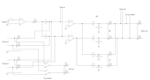
last night remember a circuit, i used a couple of years ago.
cross fader circuit.jpeg
this is your cross fader circuit.
the "fader" is used a bit different than you might expect.

You gotta use high quality opamps, since we're talking about "amplitude" of 0.5 V up and 0.5 V down or 1 Volt peak to peak. powered from a bi-polar 12 V circuit, 24 V peak to peak. sure you could use a single ended power sypply, but the you gotta create virtual ground and used DC coupling capacitors 4uF7, 10 uF. also a topic in it's own.
OPA2991 or a other OPA model. 2/3us$ a piece.

i added "headers", you can find them in the Kicad 6 library
 
Here's a pic of the inside with the mic pre in place (the small green/blue on the left, in the middle is the summing bus and on the right is the master pre)

this is how it should be
www.befaco.org mixer 2 (simple mixer)
Schematic

befaco.org hexmix
Schematic

Hexmix_front.png

it has everything you want, accept a cross fader.


Learn to use Kicad
https://www.kicad.org
KiCad's Schematic Editor supports everything from the most basic schematic to a complex hierarchical design with hundreds of sheets. Create your own custom symbols or use some of the thousands found in the official KiCad library. Verify your design with integrated SPICE simulator and electrical rules checker. Learn more.

Check YouTube video's how to make Footprints, a symbol and and joint them.
draw a circuit and turn it into a pcb.

As a starter don't try to create an entire machine, but create sections and turn to little sections in to pcb's + mounting holes (found in library),
don't forget to give these pcb's a power supply interface (holes/vias), ground vias.
you will fuck up the first pcb's, but after that ...

OSHPARK for reactive cheap purple and gold plated pcb's ... much much better than a wire salad.

You can get this PCB @ Thonk.co.uk ... and the matching pots.
 
1650577511820.png

this is how you wire normally faders (pots) for each channel.
the fader is in between 2 opamp and connected to ground on one side and the wiper to the next opamp, witch also results the sound is on the right side up.
Don't mind the resistors values, just use 10K .. and some opamps require a ceramic 10/22/47 pF capacitor in parallel, like C6 here (under R3 220k).
but you might wanna boost the sound and use a 12K resistor as R3 in this case and R2 as a 10K or make this circuit in 2 fold and have a overal gain pot before or after the channel fader.

that's why you need a osciloscope, sometimes the opamps have some "side effects" and these capacitors will remove them.
if you design your tiny pcb's give all the opamps a footprint for these capacitors and place them when needed.

InAmp - Befaco
befaco INamp V1 4 Schematic.pdf

https://www.befaco.org/out-v3/
befaco Output V3 Schematic.pdf
 
Last edited:
Thanks for the schematics and info, I understand what you're talking about.. the opamp in the schematic is to denote a preamp module (for the master pre I have schematics but they're built from kit, the mic pre is a prebuilt module)

Here's an updated schematic, the cue was accidentally post-fader.. also removed the aux channel.

mix3.jpg

i can't really read your schematic.

this is a mixer for me.
1650631741537.png
https://befaco.org/docs/Mixer/Mixer_V2.4_Schematic.pdf

the 10K resistors (R4, R2, R6, R5) stacked on top of each other in combination with 10 (R7) over the opamp (IC1A) is the mixer (SUMMING BUS).
accept in your case you would put an opamp between the input jacks and the potentiometer instead of IC1B, to not load the circuits from your sources.

the opamps are all inverting, you seam to use non inverting opamps in your circuit and it requires a different setup of resistors, not present in your schematic? also the reason to keep in mind that each time you use a opamp, you're inverting the signal ... and you gotta make sure you're right side up again in the end.

try to introduce the circuits i gave you in to Kicad and route them.
Make those pcb's will be like twice the size of a TL074 opamp and it will cost you like 7,50us$ + free shipping at OSHpark .. you pay for one and get 3.
use a calculator to move the traces dead on between the pins of the TL074, the pin spacing is 2.54, so 1.27 is the half of it.
 
Last edited:
Thanks for the schematics and info.

Just in case you didn't know what a "summing bus" is.

It's like i said in the previous post.
(R4, R2, R6, R5) and (R7), the "track" between them 10k resistor's is somewhat isolated from the rest of the circuit.
a signal entering R4 is encountering a resistance of 10K and it to weak to exit again via R2, R6, R5 (the other inputs under normal circumstance) and it will rest only one thing to do and that's to join them other signals (sum, addition or substract, mix).
R7 the 10K feedback over the opamp is there to restore the "volume" back to previous state where it entered via R4, R2, R6, R5.
Using a bigger resistor there will increase the signal and a smaller will cause to opamp to "saturate" sooner and therefor will return a smaller signal.
You might wanna use a 11K or 12K to boost the signal by 10% or 20% at some stage, overal gain.
 
Just in case you didn't know what a "summing bus" is.
Yes I know what a summing bus is.. the first build had a 10kOhm bus to sum the channels but I switched them to 220R.

There was a close-up picture but the photo host deleted it.

IMG-20200919-193305.jpg


The yellow thing on the middle below the blue PCB is the summing bus I built using solder tag boards/strips. On the left is the input side and on the right is the summing side, between there are resistors.

EDIT : found the close-up pic:

summingbus.jpg


I could've used a resistor network IC but this is easier to modify. I chose not to use summing resistors for the current build since the channels are passive (apart from the mono channel which has a preamp and 1kOhm resistors)
 
Last edited:
Yes I know what a summing bus is.. the first build had a 10kOhm bus to sum the channels but I switched them to 220R.

There was a close-up picture but the photo host deleted it.

IMG-20200919-193305.jpg


The yellow thing on the middle below the blue PCB is the summing bus I built using solder tag boards/strips. On the left is the input side and on the right is the summing side, between there are resistors.

EDIT : found the close-up pic:

summingbus.jpg


I could've used a resistor network IC but this is easier to modify. I chose not to use summing resistors for the current build since the channels are passive (apart from the mono channel which has a preamp and 1kOhm resistors)
do you know the Falstad simulator?
it's free and pretty good, it's has alot of example included, try build your circuit in there.

if you gonna be passive, you might detroy "gear" sooner or later, by loading them and what not at some time, unless they use a capacitor.
try what i suggested, by using Kicad to make 5cm x 5cm or smaller pcb's (place one quad opamp on it, header pins for power and audio, use wires to connect the pots, mounting holes on the corners) and upload them to OSHpark.com.
I've been using Scheme-it by Digi-Key but afaik it doesn't have SPICE simulation.

Passive summing has a drawback when using PFL and that is channel crosstalk when the cued channel is being introduced to the mix so the cued channel fader must be in zero position in order it to work... in theory this could be avoided by using diodes or an active summing bus.

I was thinking of ordering a small quantity of opamps and Veroboard (or similar) to do my own preamps (or an active summing amp but I'd imagine it turning out too big to fit inside a chassis with the rest of the PCBs)

There are many other quirks too but to conclude it a mixer is very interesting and rewarding DIY project imo.
I would suggest if i may to design your own "veroboard" in Kicad for the opamps.
Opamps normally have a standard pinlayout.

You make the power lines go underneath the opamp from side to side, than you can easily connect (via headers) them to each other and also include 100nF by pass capacitors.

this is what i did with the TL072 to be able to be stuck on a breadboard.
it has exactly the amount of holes (vias) you normally need for resistors and filter capacitors (very important), 100nF bypass capacitors and header pins for the breadboad.
the cost of this pcb board is less than 4€ @ OSH. garantees it will work always and no long tedious jobs soldering in between the pins of the ...

Opamp power supply.jpeg

a strip of 40 pin header, you can brake to size.
1650910968449.png

dip14 ic socket, so you can switch to higher quailty or repair/replace opamp.
1650911030949.png
 
Last edited:
I would suggest if i may to design your own "veroboard" in Kicad for the opamps.
Opamps normally have a standard pinlayout.

You make the power lines go underneath the opamp from side to side, than you can easily connect (via headers) them to each other and also include 100nF by pass capacitors.

this is what i did with the TL072 to be able to be stuck on a breadboard.
it has exactly the amount of holes (vias) you normally need for resistors and filter capacitors (very important), 100nF bypass capacitors and header pins for the breadboad.
the cost of this pcb board is less than 4€ @ OSH. garantees it will work always and no long tedious jobs soldering in between the pins of the ...

View attachment 93177

a strip of 40 pin header, you can brake to size.
View attachment 93182

dip14 ic socket, so you can switch to higher quailty or repair/replace opamp.
View attachment 93183
I was never good in designing PCBs at school (or I never designed any, I wasn't really good at manufacturing them either), that's why the perfboard.

I think screw terminals would be better for a one-off if the raster/spacing is the same (1/10" or 2,54mm), those terminal headers (turrets?) are a nightmare to solder (without female connectors, kind of like a shot in the dark).. the mono preamp had them and it was small as heck, about half the size of a matchbox (I shorted the grounds by accident and haven't figured out whether they're the same ground plane since it's all surface-mount, I accidentally ordered two of them though so I can check whether it's ok)

The SMPS I used in the 3RU mixer build had them too but they were more loosely spaced yet I still managed to short the connections.
 
I was never good in designing PCBs at school (or I never designed any, I wasn't really good at manufacturing them either), that's why the perfboard.

I think screw terminals would be better for a one-off if the raster/spacing is the same (1/10" or 2,54mm),
don't know what that is.
those terminal headers (turrets?) are a nightmare to solder (without female connectors, kind of like a shot in the dark)..
i stick them in/on the bread, drop the PCB over it and solder them, than they are straight.
you solder one pin, check if their are straight and you can still correct if needed.

i also use a "third" hand to prevent parts moving, alos includes magnifying glass..

You put the soldering iron on the spot and 1 second after that with the other hand you apply solder to the soldering iron while moving to the spot you wanna solder to drag the blob from the soldering iron to the right spot and help to heat the part. do not proceed after 4/5 seconds.
the mono preamp had them and it was small as heck, about half the size of a matchbox (I shorted the grounds by accident and haven't figured out whether they're the same ground plane since it's all surface-mount, I accidentally ordered two of them though so I can check whether it's ok)
pictures?
 
Started working on a new mixer, this is my 4th build.. it's an IP55 case I got from a local shop:

IMG-20221118-145501.jpg


First I added a mic pre module and an input jack:

IMG-20221119-175820-2.jpg


Then I tried my hand at installing a fader, this was the first time for me, also added RCA inputs:

IMG-20221120-151713.jpg


Then I proceeded to add a summing bus and stereo channel pots as well as 6,3mm output jacks (not pictured):

IMG-20221121-175551-01.jpg


EDIT: I'm looking at adding PFL, headphone output&vol, passive master EQ and master volume.. nothing too fancy as there isn't much space inside the chassis. Also a 2,1mm DC jack and supply the mic pre (and a power on LED) with a 9-12VDC wall wart.
 
Last edited:
Back
Top