Drip EQ1 Gen 4 - 60hz Hum / Buzz

GroupDIY Audio Forum

Help Support GroupDIY Audio Forum:

This site may earn a commission from merchant affiliate links, including eBay, Amazon, and others.

Vangetti

Member
Joined
Nov 20, 2018
Messages
18
Hi Everyone,

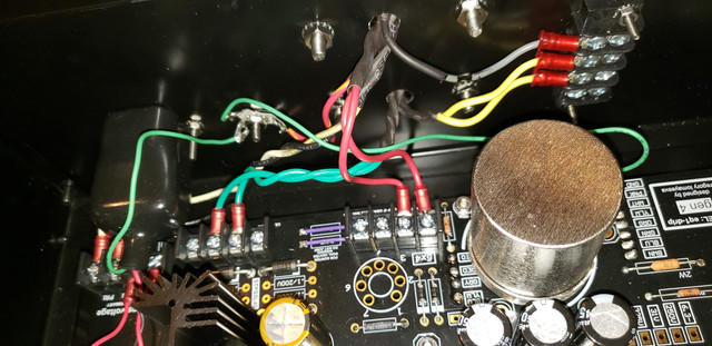
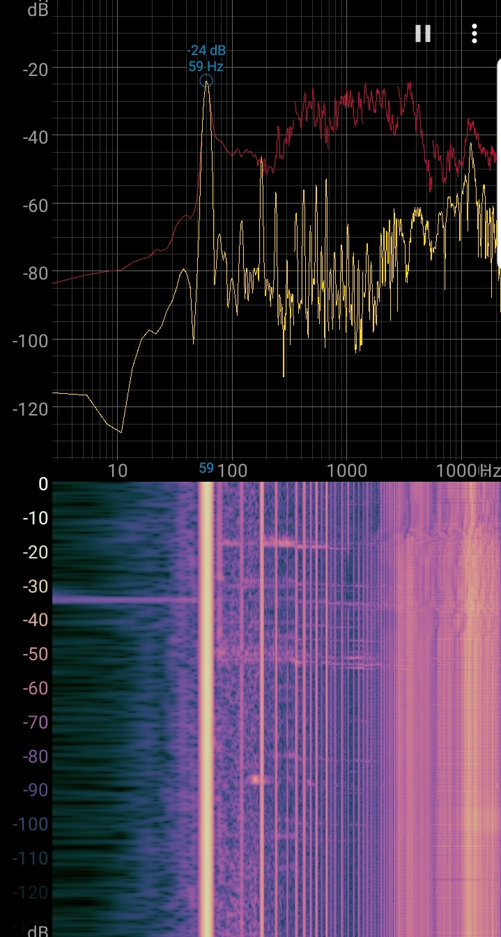
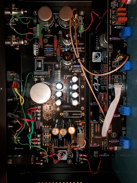
I just finished putting together my EQ1, but I have an issue. There is a 60 Hz hum that I can't figure out how to remove. I double checked that my solder joints were solid and tried to troubleshoot the unit with no luck. I also replaced the tubes, but it wasn't the solution. I could boost the 60hz hum with the EQ, so the hum must be going to the preamp tubes.

Would anyone have any idea of what the problem could be?

Perhaps a bad filter capacitor or the power transformer? I fed my guitar through the EQ1, and it did sound nice, but the 60Hz hum is annoying.

Images
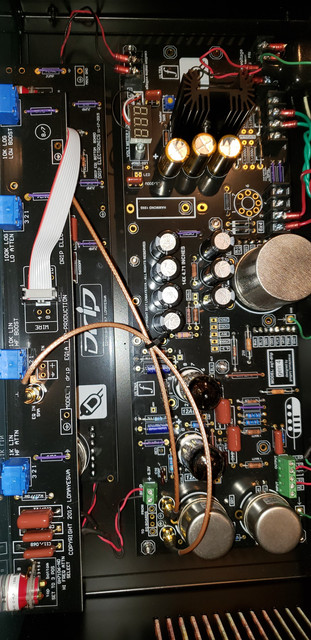
EQ1-pic-1.jpg

Eq1-pic-2.jpg

EQ1-Hum.jpg


Audio clip
https://clyp.it/zpvxi2xa?token=156ff51237ebecbfc3261e4f58a7af30
 
I'm using the continuity test mode on my multimeter and I'm getting a 0.00 reading. When I put my ear up to the transformer the noise coming from it is the same that I hear outputting to my speakers.
 
I had that same issue on version 2 years ago. I think I fixed the issue by disconnecting a front panel ground. I think there was a ground wire (to be wired to a star ground) for each front PCB. I disconnected one. Even though it was reading 0 ohms to ground, I think it was creating an issue since both front PCBs were also connected to each other via a ground wire. So, maybe try that and see if it helps. Sorry my memory isn't serving me fully right now haha

I did end up buying another one that someone else built and it had the same issue, I repeated the fix I did on mine and now they're both silent. Good luck!
 
Thanks for the info! I think both of my front panel PCBs are connected to ground via the 2 SMA cables. Should I be grounding them to the star ground? The only things I have connected to the power star ground are the  CT, mains ground and PCB ground.

For the audio ground, I have both xlrs grounded and the audio ground from the PCB.
 
Vangetti said:
Thanks for the info! I think both of my front panel PCBs are connected to ground via the 2 SMA cables. Should I be grounding them to the star ground? The only things I have connected to the power star ground are the  CT, mains ground and PCB ground.

For the audio ground, I have both xlrs grounded and the audio ground from the PCB.

Ah yeah, I didn't think about the SMA cable. The old ones didn't have those so it was a little easier to experiment. Yeah, not fully sure on the ground scenario for the V4 board without looking at a more detailed schematic. if there are any jumper wires for connecting ground you could try those. But those might not exist. You could try just disconnecting the front panel, one SMA at a time to see if disconnecting one has an effect on the hum? Could point you in the right direction. That is, ONLY DO THAT ON LOW VOLTAGE SIGNAL SMA CABLES. You don't want to mess with pulling a high voltage line that's live. But the signal going to the front should only be signal. That could help you pinpoint it to either board. If its still there, then its an issue somewhere else.
 
That's a great idea. I'll try that and see if the buzz/hum is coming from the front panel.

Thanks!
 
Unfortunately, the buzz still happens even after both front panel boards are disconnected from the main PCB.
 
Vangetti said:
Unfortunately, the buzz still happens even after both front panel boards are disconnected from the main PCB.

Ok, that's good. Now we know it's not the front. Are both of those ground wires soldered to the back of the PCB the same ground plane? If so, it could be those two ground competing. Although I can't really see where they're going.
 
Knotty said:
Ok, that's good. Now we know it's not the front. Are both of those ground wires soldered to the back of the PCB the same ground plane? If so, it could be those two ground competing. Although I can't really see where they're going.

I have three wires attached to the star ground.

IEC(18 Gauge Ecowire), Transformer (Red/yellow wire), PCB(18 Gauge Ecowire).

For the audio ground, I have both XLRs and the PCB audio ground.

scott2000 said:
Maybe something wonky with the heaters?? Is there any documentation on this build?

Unfortunately, I don't have any documentation for the build. I just have a few videos that I found online and pictures on the drip website. Also, some pictures I found on Reverb.
 
Would it make a difference if I drilled my own ground hole instead of using the one provided? It looks like the one predrilled into the back panel is a little too big for my #6-32 screw. Could that be a cause of the hum?
 
Vangetti said:
Would it make a difference if I drilled my own ground hole instead of using the one provided? It looks like the one predrilled into the back panel is a little too big for my #6-32 screw. Could that be a cause of the hum?

Check resistance to chassis from someting going to that point - if its more than a few ohms (would be a lot more, possible an open, if the screw is not making contact) .

Gustav
 
I drilled a new ground hole and got a bit lower resistance when checking between grounds, but it looks like it did not make a difference. I'm not sure if the issue is with the case anymore all the grounds look like they have good continuity.
 
Yeah, the version 3 ran on AC, but the gen 4 board is now on DC. I'm using a Hammond 270BX transformer. The CT is supposed to be the red/yellow wire that I have lugged to the star ground.
 
scott2000 said:
I'm losing it I guess. I just looked at the DRIP site and see there is some documentation on this build???////At least some initial build stuff//

https://www.dripelectronics.com/drip-eq1-pultec

.... I'm sure I didn't see anything before.....

I ran into the same scenario. I would google the drip eq1 and found older documentation. The schematics that are uploaded on the drip website are the original Pultec schematics.

eqp-1a_schem.jpg


I don't understand why on the PCB silkscreen has  .1/220V capacitors in the 6.3 power section,  but on the finished builds on drip's website, they're not there? Do you think I should put them in and test it out? Also, would it be better to use the 6x4 rectifier tube instead of the 1N4007 diodes?

I found a build that someone completed with only 2
 
Back
Top