Hi,
I have on the bench a Dynacord EC504 with almost no "DURATION" (feedback)
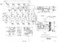
What is currently going on is that the signal at the "RETURN" (B1) is much stronger compared to the signal at "DURATION" (B2). I have no Idea if this should be like that.
When I'm injecting a 1kHz at 40mV sine wave directly to B1 I'm getting 600mV at the output of I001.
When I'm injecting a 1kHz at 40mV sine wave directly to B2 I'm getting 600mV at the output of I002.
So I can tell both op-amps are working as they should.
If I'm getting it right, the signals at those points (B1 and B2) come from the playback heads to the head amplifiers and from there to the "heads switching board". From the "head switching board" the signal goes to B1 and B2.
Since the dry signal goes to the output and I'm getting the echo (without the duration / feedback) and since the VU meter and the OL LED are working I can tell that the amplifier feeding the heads (board 82051) is working well and the bias voltage is correct (I've tested it with a scope).
I've noticed that the signal level drops from 600mV to 40mV at point B3 (at the other side of R035 the signal is strong and the resistance is 21.86K R so it's not the resistor that drops the volume.
What can cause this drop on the side of R036, C024?
Anything else that might be worth to test?
I have on the bench a Dynacord EC504 with almost no "DURATION" (feedback)
What is currently going on is that the signal at the "RETURN" (B1) is much stronger compared to the signal at "DURATION" (B2). I have no Idea if this should be like that.
When I'm injecting a 1kHz at 40mV sine wave directly to B1 I'm getting 600mV at the output of I001.
When I'm injecting a 1kHz at 40mV sine wave directly to B2 I'm getting 600mV at the output of I002.
So I can tell both op-amps are working as they should.
If I'm getting it right, the signals at those points (B1 and B2) come from the playback heads to the head amplifiers and from there to the "heads switching board". From the "head switching board" the signal goes to B1 and B2.
Since the dry signal goes to the output and I'm getting the echo (without the duration / feedback) and since the VU meter and the OL LED are working I can tell that the amplifier feeding the heads (board 82051) is working well and the bias voltage is correct (I've tested it with a scope).
I've noticed that the signal level drops from 600mV to 40mV at point B3 (at the other side of R035 the signal is strong and the resistance is 21.86K R so it's not the resistor that drops the volume.
What can cause this drop on the side of R036, C024?
Anything else that might be worth to test?