EF85 Compressor from scratch

GroupDIY Audio Forum

Help Support GroupDIY Audio Forum:

This site may earn a commission from merchant affiliate links, including eBay, Amazon, and others.

DaveP

Well-known member
Joined
Nov 8, 2005
Messages
3,028
Location
France
I'm planning to design and build a compressor based on the EF85/6BY7 Tube.

Years ago I was given 21 NOS EF85's, half are Mullard and half Siemens.  They are  unusually good remote pentodes, but they went out of fashion very quickly with radio manufacturers who went for the EF89 instead.  The reason was that the gm was just too good for their radio application and the EF89 was used instead because its gm was about half of the EF85.  This was unfortunate for the manufacturers who had large stocks of EF85's that they couldn't sell, but good news for us because there are lots of them and they are cheap.

When wired as triodes they leave a 6386 in the dust.  gm 7.5 (4.0), mu 32 (17).  Read this thread to see what PRR said about them back in 2008:-
http://groupdiy.com/index.php?topic=30349.msg368001#msg368001.

His post was an inspiration but I can't decide on the best way to use them.  I could make a conventional pentode matched pair, even make in stereo, or I could make a 660 copy and let the gm rip with four/side.  PRR did a back of an envelope design which established the design principles, but I found out during testing that the rp reduces the gain from his figures when used as a triode, (pentode is fine).

I would be very interested to hear what  members think before I go any further, also whether PRR has modified his ideas since then.

Best
DaveP
 
Hi Dave

Unfortunately I'm not a tube guy, not because I don't like tool using them, but just don't have the tech background to be accurate when talking "tube"
Yeah I know it's not a good start for me to talk about your project...
I have a quick look at PRR post, I understand only 10%, but I get some concept.
What I just want to say is: if you want to dev "from scratch" a new design just go!!!
With Ian that just "like" you and a PRR around you won't be alone.
Give us fresh air  :) I become bored about "clone"  :-X

Best
Zam
 
zamproject said:
With Ian that just "like" you and a PRR around you won't be alone.
Give us fresh air  :) I become bored about "clone"  :-X

Amen!  And the rest of us will chime in where we can, even if it is just to say "keep up the good work"!
 
Jazbo8,

Vielen Dank für die Schaltung.

DaveP

Yes it's about time I stopped making clones.

Best
DaveP
 
jazbo8 said:
Same but different...  :-*
Yes, first because it's a compressor-expander, governed by the setting of the 1Meg trimmer , second because it's a consumer-oriented product, with rather long attack time and single-wave rectification (good for easy-listening, but not for peak protection).
 
This is problem number one:

After testing the tube triode-wired at full gain, I found the mu was ~32 and gm 5.4, so rp/ri is 5.9k.  Using the standard gain equation and a 4.7k plate/anode resistor I get a gain of 14.1.  When the tube is paralleled 4/side, the mu stays at 32, the gm goes to 21.6 and the rp goes to ~1.5k, this makes the gain 24.3, all well and good.

The problem arises from what happens under gain reduction.  With about -7V on the grid the gm drops to a tenth at 0.54 and mu drops a little to 27 and rp goes to 50k.  One tube gives a gain of 2.3, but when the 4 tubes are paralleled the tube parameters go to mu 27, gm = 2.16 and rp goes to 12.5k, which gives a gain of 7.4.  So the gain reduction is compromised by paralleling.

One tube/side gives a GR of 14.1/2.3 = 6.1 or 15.7dB, but 4 tubes/side gives a GR of 24.3/7.4 = 3.3 or 10.3dB, not what I was anticipating but on reflection it's understandable.  PRR said pentode mode was attractive, we can see why :-\

Best
DaveP

 
DaveP said:
This is problem number one:

After testing the tube triode-wired at full gain, I found the mu was ~32 and gm 5.4, so rp/ri is 5.9k.  Using the standard gain equation and a 4.7k plate/anode resistor I get a gain of 14.1.  When the tube is paralleled 4/side, the mu stays at 32, the gm goes to 21.6 and the rp goes to ~1.5k, this makes the gain 24.3, all well and good.

The problem arises from what happens under gain reduction.  With about -7V on the grid the gm drops to a tenth at 0.54 and mu drops a little to 27 and rp goes to 50k.  One tube gives a gain of 2.3, but when the 4 tubes are paralleled the tube parameters go to mu 27, gm = 2.16 and rp goes to 12.5k, which gives a gain of 7.4.  So the gain reduction is compromised by paralleling.

One tube/side gives a GR of 14.1/2.3 = 6.1 or 15.7dB, but 4 tubes/side gives a GR of 24.3/7.4 = 3.3 or 10.3dB, not what I was anticipating but on reflection it's understandable.  PRR said pentode mode was attractive, we can see why :-\

Best
DaveP
The flaw in your analysis is that the plate load should dominate over internal resistance, in order to make gain directly dependant of Gm only (about). I would say each tube should see about 2-4k load. That makes for a low-Z primary, which is good for HF response. Indeed pentode mode would justify a very different arrangement, but would it be better in the end?
 
When you used one tube your plate load Rp was approximately equal to rp and when gm dropped to 1/10 you got 15db gain reduction. To keep the same amount of gain reduction with four tubes in parallel you should change the plate load equal to rp again. Or use the tubes in pentode mode where rp is always much higher than the load and mu doesn't matter.

 
I would say each tube should see about 2-4k load. That makes for a low-Z primary, which is good for HF response. Indeed pentode mode would justify a very different arrangement, but would it be better in the end?

I take it you mean they just see the primary Z of an OPT, they can't all have a load resistor?  PRR's idea was for a low value load resistor like 4-5k, but he didn't elaborate on the parallel tubes option.

Heikki,
If I reduce the load resistor to ~1k then the gain advantage of using parallel tubes is lost, apart from noise reduction aspect.

best
DaveP
 
If you have 4 tubes parallel for each side and use 1.5k load resistors and couple it with a capacitor to a 8k:600 ohm output transformer. Gain would be 11dB from the grids to 600 ohm load. Wouldn't that be enough for 660 type compressor?
 
DaveP said:
I would say each tube should see about 2-4k load. That makes for a low-Z primary, which is good for HF response. Indeed pentode mode would justify a very different arrangement, but would it be better in the end?

I take it you mean they just see the primary Z of an OPT, they can't all have a load resistor? 
Whatever they see, their share should be about 2-4k. Indeed, seeing a transformer has advantages over seeing only resistors.
PRR's idea was for a low value load resistor like 4-5k, but he didn't elaborate on the parallel tubes option.
I take it he meant for each tube to see that much.
If I reduce the load resistor to ~1k then the gain advantage of using parallel tubes is lost, apart from noise reduction aspect.
If the load is a xfmr, using a quad allows a reduction of impedance of 4:1 for the primary,; which means the output voltage will be twice higher.
If you use resistors, you will still have an improvement due to quadratic combination of noise. The big issue there is that the noise performance of the subsequent stage cannot be neglected.
 
> PRR said

Not as dumb as I look.

> didn't elaborate on the parallel tubes

Nobody asked.

Though I would think that if 5K is happy for one tube, four tubes ought to be seeing 1K-2K, not 5K.

Thought experiment:

Make the load 1 Ohm. What is the gain variation? *Directly* proportional to Gm.

Make the load infinity (with infinite B+). What is the gain variation? Proportional to Mu, or essentially none.

Taking the load similar to full-up Rp ensures you lose 6dB of GR.

So load must be low. But no/low-load is no/low-output. There's a compromise somewhere. IMHO this tube can give "interesting" output with a single pair; but if you want more (and have a box-load), paralleling is a slow but sure way to higher power output. (And averages tube variations.)

 
One key question you need to consider is the operating range. Looking at the datasheet curve for gm vs Vg it seems clear that gm can be varied by more than three orders of magnitude which gives a potential gain range of well over 60dB. For a compressor/limiter you are not likely to need a gain range of more than 30dB so there is quite a choice in operating point. It is also clear from the same curves that the slope varies considerably so perhaps there is a possibility of altering the ratio by moving the operating point. The steepest part of the curve seems to be at the higher gm values.

http://www.r-type.org/pdfs/ef85.pdf

Cheers

Ian
 
You are dead right Ian, when you transfer the voltage points from the current chart to the gm chart there is quite a curve and an optimum point around the 150~200V mark for the highest gm drop.


The only snag in moving it too far is that you need a greater negative voltage to reduce the gain.

best
DaveP
 
DaveP said:
The only snag in moving it too far is that you need a greater negative voltage to reduce the gain.

best
DaveP

The other snag is gm gets really small. You need to find a path between adequate S/N and low distortion/avoiding overload. If you use a 1K Rp for instance, at the max gm of about 6mA/V your gain is  6. 20dB of gain reduction will drop this to 0.6 but presumably the input signal will be about 20dB higher if we are limiting so the output at the plate is the same. Whether this is a good starting point or not depends on where you want your threshold. Many of the 'classic'  broadcast limiter designs have a threshold around 0dBu and with a 20:1 limit ratio would reduce a +20dBu input to +1dBu output. A nominal gain of 6 is about 16dB so the 0dBu input signal becomes +16dBu out of the vari mu tubes and a +20dBu input becomes +17dBu so probably not so high as you have to worry about distortion.

Lots to think about.

Cheers

Ian
 
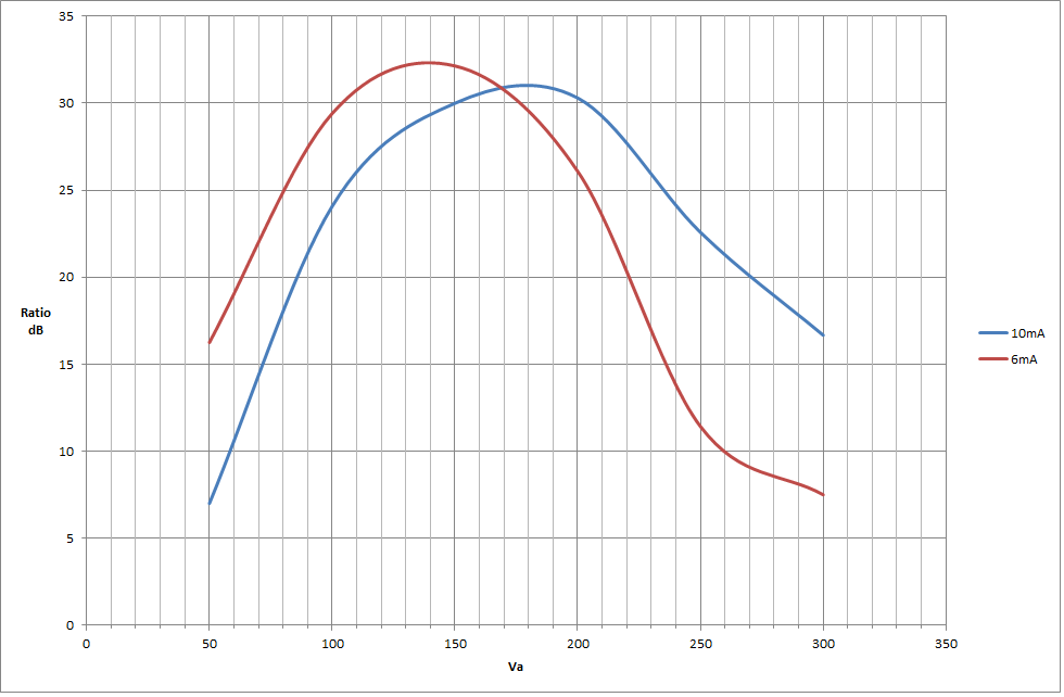
OK, I've done some number crunching.
This is a table to illustrate how the gm changes at various g2 voltages.  The ratio is, for example, the gm at 10mA/gm at 1mA, this follows on with 8mA/0.8mA, etc.etc.


The figures for 300V were too poor to be included, as were the early figures for 50V.
The best operating points appear to be 200V@8mA, 150V@8mA  100V@4mA

The maximum power dissipation is 2.5W, so 200V@8mA is OK at 1.6W, but the gm is actually higher at 100V all the way down.
Comments welcome.
Best
DaveP
 
If you have 4 tubes parallel for each side and use 1.5k load resistors and couple it with a capacitor to a 8k:600 ohm output transformer. Gain would be 11dB from the grids to 600 ohm load. Wouldn't that be enough for 660 type compressor?
The gain of a 660 was specified as 16dB so I would want to equal that if possible Heikki

So load must be low. But no/low-load is no/low-output. There's a compromise somewhere.

I am sure you are right, PRR

DaveP
 

Latest posts

Back
Top