EF85 Compressor from scratch

GroupDIY Audio Forum

Help Support GroupDIY Audio Forum:

This site may earn a commission from merchant affiliate links, including eBay, Amazon, and others.
> snag is gm gets really small

We want that.

The snag is that maximum output must happen at *minimum* current. If you go down to 0.1mA to get enough GR, you won't have enough output to drive a transformer; even resistance coupling gets lame. Nevermind the Fairchild approach of driving the output straight off the VCA tubes.

I use a '2mA' low-limit for fast estimations into ~~10K load. This keeps the THD small. After picking likely tubes, then a detailed analysis would show just how much output can be supported for what range of GR.
 
If I work backwards from the output, I may be able to narrow down the choice a little.
The 660 has an output of +8dBm @600 ohms, which translates to 1.95V.

If I use this as my benchmark and take Heikki's advice and use an 8k:600 OPT, then I need 1.95V * 3.65 = 7.12V output from my tubes.  As the tubes are push-pull that will need 3.56V from each side of 4 tubes.

If I use Rp = 1.5k, then my full gain is 16 and my low gain is 0.5 .  for -30dBmax GR

Input level would then be 3.56/16 = 0.222V for full gain and a GR max of 7.12V assuming level is made up, this would need the grid to be at 10V to enable that headroom, quite a tall order!

For example: the grid voltage for 200V@8mA is -6.5Vg1

I've gone through this to check my methodology, but in fact all these figures refer to pentode connection but triode connection increases gm by 25%, so all this will have to be checked out on the bench.

As Ian said, there is a lot to think about.  Time for bed :-\

best
DaveP

 
Remember a 660 manages +8dBm@600 with a 50K:600 output transformer too.  FWIW. 

Everyone today will want higher output, certainly, which may be a separate output stage. 
 
Doug,

I was planning to use a 10k:10k IPT, will that be OK?

What output level would be required in the studio, something like +24dB?

best
DaveP
 
A/D converters are often calibrated so that 0dBFS is somewhere between +18dBu and +24dBu. But +24dBu output is probably not needed from a limiter. There's also very little need for the ability to drive 600 ohm loads nowdays. 1:1 output transformer for the 660 type plan would solve the problem with output level.
 
The question is, what is the point of it all?
If I take the easy path with just a pentode pair, then it's just like all the rest and is unlikely to have any special benefits regarding sound.  If I take the triode pair route, then the same thing applies except it will be more like 6386 compressors.  If I go the 4/side route I get the triode harmonics plus the 660 non feedback sound  and lower noise too.
I may have almost convinced myself ::)

Best
DaveP
 
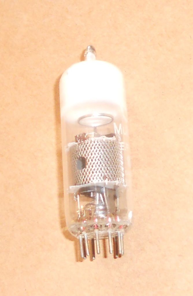
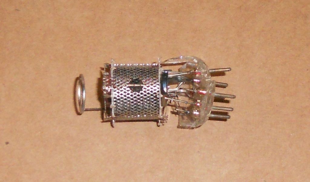
Having decided that the EF85's will be triode-wired, I broke open one that had lost its vacuum from a crack from a pin.


I wanted to check whether the suppressor grid could stand being tied to the plate as well as the G2.


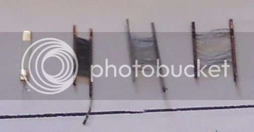
To my surprise, the G3 looked thicker than the G2 wires, so problem solved.

Here are the nice frame grids from left to right.  Cathode, G1, G2, G3.


G3 got mangled when I cut the plate off, but you can just make out the wire thickness, my little camera doesn't like close-ups much.
Best
DaveP
 
DaveP said:
Having decided that the EF85's will be triode-wired, I broke open one that had lost its vacuum from a crack from a pin.

That's some quality firsthand research!

Condolences for your loss, DaveP.
 
That's some quality firsthand research!

Only the best for GDIY 8)

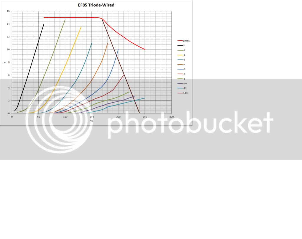
I decided to test the Vp/Ip characteristic to give me an idea of what's going on.


I was quite pleased because the characteristic gave the same mu/gm/rp as I had measured other ways.  There was a lot of "wobble" in the figures for the higher negative voltages, which was the same after I did them twice, so I figured it must be due to the variable spacing of the remote grids.  I left them as is .

The red line at the top is a combination of the 2.5W power max and the 15mA current max.

The brown load line marked 4.8k is my proposed load for the 4 tubes/side (4.8/4=1.2k)  which is a convenient preferred value.

As PRR predicted, you can see that for a change from 10mA to 1mA the voltage only drops 43V which should help reduce thumping, I plan to use a regulated B+ supply for this.

With the load line at 240V, it makes it possible to drive the tube's Vg1 down to its lowest point of around -30V.  I have not plotted those figures as it was just too tedious!

I think this project should probably be moved to the compressor section now, but I don't know how this is done :-\

Best
DaveP


Latest posts

Back
Top