EMI RS124

GroupDIY Audio Forum

Help Support GroupDIY Audio Forum:

This site may earn a commission from merchant affiliate links, including eBay, Amazon, and others.

ed rees

Well-known member
Joined
Nov 1, 2009
Messages
108
Hi,
Anyone have any RS124 info? I think I've got it all figured out with correct information. I'd love to see a copy of John Hinson's removed RS124 web page, if anyone saved it. I'm trying to get an internal pic of a Hinson unit to check against, also...

Not sure how soon, but I'm going to build one, then post a build thread and schematics, layouts, etc... here.
Then you guys can help me weed out any mistakes, or make some improvements to the design! Or if someone then wants to PCB it, I'm all for it.

NEVERMIND: My work here is no longer necessary.  ;D
 

Attachments

  • RS124X1Web.jpg
    RS124X1Web.jpg
    43.2 KB
I suppose the question is wether or not you've gotten the correct info, which I suppose you know, since if you have, you musn't be far from the source, ie, and old emi tech or someone who has reverse engineered one. I haven't at least seen anything floating around on the web over the years.
 
So far I have: A list of the correct tubes, Rotheu's neon bulb balance circuit, common VK1 schematics (which are quite obviously a close RS124 derivative), real RS124 response curves, and lots of text info I've gotten from people "in the know".

I feel we should be able to get it really close with all this, atleast a very good 'poor mans' RS124. :-\
 
Yeah they definitely have lots of color. Some people love it, some hate it. Not much of a multi-tasker, for sure.

I like the plugin, I'm willing to risk several hundred dollars to see how I like a real(ish) one.

 
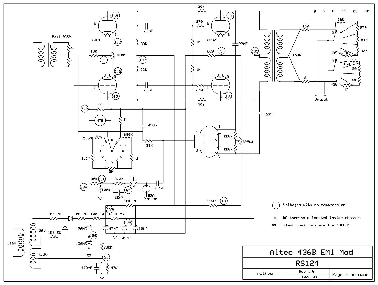
Here we go!!! Nice sound, especially on the bass, but release times are way to slow IMHO. The key to stability and solving the problem with thumbs original Altec 436B had is those two 39K plate to plate feedback resistors, the rest is nothing special.

Altec436EMIModRS124.jpg
 
Here we go indeed!  ;D  Ordering my parts tomorrow... and starting on my chassis.


Hi,

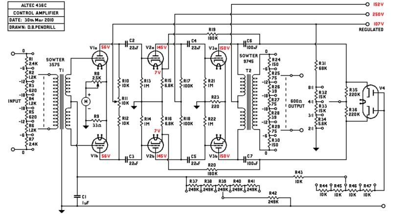
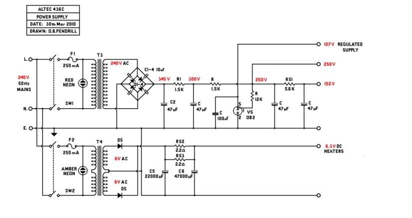
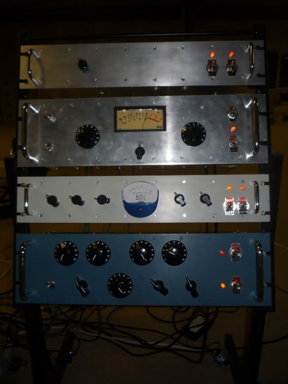
I made one of these earlier in the year, I put in an extra tube to cure the stability problem and my own balance circuit, I didn't find the neon necessary but I had to select a balanced 6BC8 to get it right (had to buy 10 to find one).  By using a regulated supply from the UA175 you can extend the compression ratios obtainable up to 8:1, easily selectable as in my schematic.

436ControlAmp.jpg


436PowerSupply.jpg


Rack-1.jpg
 
Great work here!

something i did to the same circuit with great results: adding an intersatge transformer.
with it,i could bring down the SC cap to 0.22uF with 150k release and 18k attack resistors.
very fast release without stability problems.built a few of these and love what they do.
 
This is interresting. Looks like a nice P2P-project.

Mich: Where did you add the interstage trasnf ? and what ratio/impedances.

 
Cool design too, Mich! Is that a real Altec meter, or a re-purposed Jewell MM2? Funny, they still make that same old meter.
 
MrZpliff said:
This is interresting. Looks like a nice P2P-project.

Mich: Where did you add the interstage trasnf ? and what ratio/impedances.

I'm guessing right after the 6bc8..
 
The interstage goes between the first and second stage (replacing the .022uF coupling caps)

i used a military utc that i had 1K:4.5K(1:2.12 turns ratio) with lots of henrys...and  zobel network on the output to flaten the response.

you can try anything you have on hand - the bigger core the better - and more inductance gives you more low end(simplifying..)
 
MagnetoSound said:
@rotheu, what is the origin of this schematic? Is it simply your own variation on a theme, or did it come from someone "in the know"?

Someone "in the know" ;)
 

Latest posts

Back
Top