You are using an out of date browser. It may not display this or other websites correctly.
You should upgrade or use an alternative browser.
You should upgrade or use an alternative browser.
EMI TG 12434 "Spreader" Schematic
- Thread starter Strawtles
- Start date


Help Support GroupDIY Audio Forum:
This site may earn a commission from merchant affiliate
links, including eBay, Amazon, and others.
")
also curious about this circuit.
does anyone know if this design lets you manipulate the stereo program from full mono to full stereo width?
or only fixed "in between" settings ? also curious to know if it has/had automatic gain compensation when used in wide stereo settings?
cheers
does anyone know if this design lets you manipulate the stereo program from full mono to full stereo width?
or only fixed "in between" settings ? also curious to know if it has/had automatic gain compensation when used in wide stereo settings?
cheers
I'll explain how the passive spreader control in the REDDs worked. Maybe someone can design a spreader from this info?
The left and right mics go through a pair of S&D transformers.
Then the sum and difference lines each has it's own bridged T fader.
This is followed by the spreader, which is just another set of bridged T attenuators connected to work inversely.
After this is the shuffler, which would be desirable and was probably included in the TG unit.
Then the signals go through another set of S&D transformers to make them back into Left and Right signals.
For the shuffler, this looks like a 600 ohm version, no idea what it's from but it has the same topology as the Redd.17's 200 ohm shuffler.
http://www.richardbrice.net/EMI_shuffler_circuit.GIF


ruffrecords
Well-known member
This company makes the 'Shuffler' which is intended to improve stereo imaging and was apparently present in the REDD 47 desk era. There is also some fairly detailed info on how it works:
http://www.phaedrus-audio.com/brideoffrancinstien.htm
Not the same thing at all BUT it does work using sum and difference signals which is the way the 'Spreader' is supposed to work.
Cheers
Ian
http://www.phaedrus-audio.com/brideoffrancinstien.htm
Not the same thing at all BUT it does work using sum and difference signals which is the way the 'Spreader' is supposed to work.
Cheers
Ian
The only possibly hard part would be determining the value of the spreader's inverted bridged-t attenuators. I'd have no idea where to begin on that. The values are unmarked on the Redd17 schematic I have.
The rest is cake. 600Ω S&D matrix > ?spreader? > that 600Ω shuffler > another S&D matrix. Maybe throw in some TG make-up gain, if that's the sound you're looking for.
All the Redd37 manual says about them is the "-6dB...0...+6dB spreader on the Redd.17 has been replaced with a -12dB...0...+4dB type on the Redd37."
I'll keep looking into it.
It just dawned on me. The .37's spreader almost had to be a pair of 16dB bridged-T attenuators connected inversely, though the '0' position was really -4dB. So relatively, -12, 0, and +4 settings could be attained passively.
It might help to mention that REDD stuff was referenced to .447v for 0dB at 200ohms.
It might help to mention that REDD stuff was referenced to .447v for 0dB at 200ohms.
Michael Tibes
Well-known member
A more detailed description is here (scroll down a bit):
http://www.phaedrus-audio.com/FABs.htm
This seems to be the theory behind it:
http://www.phaedrus-audio.com/stereosonic.pdf
A bit of a math overload for me, but maybe someone get's a grip on it?
Michael
http://www.phaedrus-audio.com/FABs.htm
This seems to be the theory behind it:
http://www.phaedrus-audio.com/stereosonic.pdf
A bit of a math overload for me, but maybe someone get's a grip on it?
Michael
clintrubber
Well-known member
Interesting topic!
This popped up, hope it shows up without login over there ?
Otherwise, the message itself:
http://www.diyaudio.com/forums/analog-line-level/146693-john-curls-blowtorch-preamplifier-part-ii-722.html#post2392562
This popped up, hope it shows up without login over there ?
Otherwise, the message itself:
http://www.diyaudio.com/forums/analog-line-level/146693-john-curls-blowtorch-preamplifier-part-ii-722.html#post2392562

clintrubber
Well-known member
As the linked message states it's a simple implementation.
But it _does_ realize 'the' transfer (didn't check how accurately, & assuming low-Z drive (say <600) & Hi-Z load (>20k).
But doesn't address the phase-compensation.
But it _does_ realize 'the' transfer (didn't check how accurately, & assuming low-Z drive (say <600) & Hi-Z load (>20k).
But doesn't address the phase-compensation.
clintrubber
Well-known member
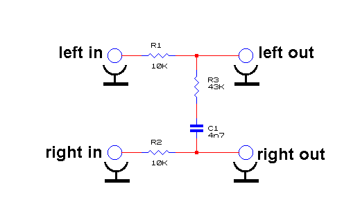
Strawtles said:honestly I'm a little skeptical about how it could work this circuit
Or is your question mainly w.r.t. how ?
The crosstalk is 'created' started from a certain freq and upwards (increasingly) by the capacitor...
... and then 'limited' from a certain freq on to a certain constant crosstalk (flat part of the transfer) by the resistor in series with the cap.
See the freq-transfer here in the middle of the blue-ish figure:
http://www.richardbrice.net/franci_revisited.htm
This is the "mirror-image" of what used to be called "Elliptic Equalizer", because it was used in vinyl mastering for reducing the amplitude of the stylus' vertical movement (failure to do so would have presented the risk of discontinuous groove). Vertical amplitude is directly related to out-of-phase LF signals.Strawtles said:honestly I'm a little skeptical about how it could work this circuit
Here the high frequencies are partly mixed together, leaving LF untouched.

clintrubber
Well-known member
clintrubber said:But doesn't address the phase-compensation.
Some brief further reading gave me the impression that this mentioned phase-compensation isn't relevant for the shown simple crosstalk implementation.
For the more elaborate one with Sum & Difference, Lowpassing & reverting back to L & R the phase compensation would be required.
Similar threads
- Replies
- 0
- Views
- 278