EQN build thread

GroupDIY Audio Forum

Help Support GroupDIY Audio Forum:

This site may earn a commission from merchant affiliate links, including eBay, Amazon, and others.
The leaded holes are over 6mm so it has more do do with the width of the part.. Buy 200 of what you found and send me some.

Here is some from newark as well
http://www.newark.com/multicomp/mccfr0w4j0475a50/res-carbon-film-4-7mohm-250mw-5/dp/58K5059
Digikey
1/6W
http://search.digikey.com/scripts/DkSearch/dksus.dll?Detail&name=4.7MEBK-ND
1/8W
http://search.digikey.com/scripts/DkSearch/dksus.dll?Detail&name=CF1/84.7MJRCT-ND
 
Peter,

What was the part number for the DC/DC thing incase someone wants to hang that way? Helping someone find parts for there build, and I passed on by it wherever it is...

Kaz

 
kazper said:
Peter,

What was the part number for the DC/DC thing incase someone wants to hang that way? Helping someone find parts for there build, and I passed on by it wherever it is...

Kaz
Kaz,

It's TDK LAMBDA CC6-2412DF-E from Peter's BOM.

Cheers, Jeff
 
jsteiger said:
kazper said:
Peter,

What was the part number for the DC/DC thing incase someone wants to hang that way? Helping someone find parts for there build, and I passed on by it wherever it is...

Kaz
Kaz,

It's DC-1 TDK LAMBDA CC6-2412DF-E from Peter's BOM.

Cheers, Jeff

Woahhh apparently I'm smoking something and just don't know it. Thanks for the number though.


Bad news is it's coming up as a obsolete part now....at least on mouser
 
kazper said:
Bad news is it's coming up as a obsolete part now....at least on mouser

Others (Digikey, etc.) have it listed not as obsolete, but out of stock...

Expensive little bugger - $15.
 
having some problems tracking down the bc184c at my usual places...
is the bc549c an ok replacement?
a quick look at the datasheet revealed that the bc184c has/likes a collector current of 500ma and the bc549c only 100mA. That a problem?

thanks!
 
I bought my BC184Cs from these guys:

http://cgi.ebay.com/BC184C-BC184-Transistors-Sinclair-Computers-10-Pack-/250616104735?cmd=ViewItem&pt=UK_VintageComputing_RL&hash=item3a59e2471f

Cheers,

G
 
Denyle Guitars said:
Is the API 2623 cool for the output transformer?

I think a custom made tranny based on the LO1166 is in the works and will be sold by hairball audio.

as for the small format pots....having trouble finding the PRV6 series, but found RV6 instead:
will this one fit the bill?
http://uk.rs-online.com/web/search/searchBrowseAction.html?method=searchProducts&searchTerm=2508745105&x=0&y=0
or indeed this one?
http://www.banzaimusic.com/Alpha-9-PC-NUT-10k-lin.html?quantity=1
 
Hi Peter,
starting to populate the board now - very comfortable to solder!
Thanks for the crucial advice regarding the mini resistors.

Would you care to elaborate on the following bits....
R29 TBD gain set -how to determine this value?
R18 220k not used -this means just leave out, not a jumper right?
R17 2k7/6k8 -again how do I determine the correct value?
I guess the amp-pins need to be bent by 90 degrees to fit the sockets,
would be great if you have a picture that shows how it's done right.
RV4/5 -what is the alignment procedure for these trimmers? is it similar to the 'symmectrical clipping' process on the 1290 preamp?

Cheers
Briomusic

ETA one more question regarding the orientation of the 68uF on the ampboard...on this picture:
ampol.jpg

C8 has the plus sign on the left and slightly to the bottom, on the actual ampboard this cap is positioned vertically, so just to verify, plus side pointing towards/or away from the connector pins?
 
Thanks denyle, had a look at the BA284 schematics and the traces on the pcb, and what you say makes sense!

Have you (or anyone else for that matter  :) ) had a chance to fire up your EQN yet? I am pretty close to finishing, but am a bit weary about powering up without answers to the questions above.
 
well as my 'journey' continues (unfortunately currently a journey without 'purpose', geddit)
i actually powered up today - no smoke  :D
i am even getting some very tinny sounding audio, which disappears when i disable the eq
(it's obviously not a hard-bypass, I am still trying to figure out what the 'eq in' switch does, not easy without schematics etc...)
however, all the frequency bands seem to be working i can boost and cut to my hearts content, can't really make any judgement about the sound as something is clearly going wrong somewhere.
I swapped the 'BA284'style ampboards for two different ones from the other kit - this didn't change anything.
I am currently looking at the input stage (is there even one? can't locate the BA283 that would be found on the original)
or output stage.
RV4 seems to be some sort of input level, RV5 seems to be the 'symmectrical clipping' adjuster same as in my EZ1290.

I can't believe noone is posting apart from me and denyle, I think quite a few kits were sold. come on guys, pipe up :)
brioEQn1.jpg

(the trafo is a VTB 1847 which I am using to test the eq while waiting for the EA1166)
 
briomusic said:
...I can't believe noone is posting apart from me and denyle...
We are all anxiously awaiting while yourself and Denyle pave the way...work out any kinks and so on!  ;D

I have yet to order the balance of my parts, aside from already receiving Colin's parts kit. I am trying to tie up a few other loose ends before starting more loose ends.  8)  I'm sure I speak for a few others too.

Keep up the good work guys. I hope you figure out the "tiny" sounding situation. Also, congrats on no smoke. That is always a plus.  ;)

I remember Denyle mentioning a 2623-1 for output tranny. Is there any DC present? Probably not good for a 2623-1if it's more than a few mA.

Cheers, Jeff
 
Guys.... you wouldn't believe the chit I've been stuck under, but you now have my attention.
I'll start working through... let me wake up first.
 
Would you care to elaborate on the following bits....
I'll have a pop
R29 TBD gain set -how to determine this value?
Depending on how the output transformer ratio ends up, we'll be using something from 600R-1k2.
We also have a fader trimmer to fine tune.
R18 220k not used -this means just leave out, not a jumper right?
Leave it out.
R17 2k7/6k8 -again how do I determine the correct value?
Different schematics have different values. This is the q setting resistor for the mid inductor. I used 6k8.
I guess the amp-pins need to be bent by 90 degrees to fit the sockets,
would be great if you have a picture that shows how it's done right.

I'll get a pic up.
RV4/5 -what is the alignment procedure for these trimmers? is it similar to the 'symmectrical clipping' process on the 1290 preamp?
Exactly.
 
well as my 'journey' continues (unfortunately currently a journey without 'purpose', geddit)
Chortle
i actually powered up today - no smoke
Marvellous 
i am even getting some very tinny sounding audio, which disappears when i disable the eq
(it's obviously not a hard-bypass, I am still trying to figure out what the 'eq in' switch does, not easy without schematics etc...)

I'll get an abortion of a schematic up...... I've been avoiding it like the plague.
however, all the frequency bands seem to be working i can boost and cut to my hearts content, can't really make any judgement about the sound as something is clearly going wrong somewhere.
No answer to that until I get my thinking cap on.
I swapped the 'BA284'style ampboards for two different ones from the other kit - this didn't change anything.
ditto
I am currently looking at the input stage (is there even one? can't locate the BA283 that would be found on the original)
or output stage.

The input tx's output goes to the eq in switch and from there either to the eq section, or the output stage.
RV4 seems to be some sort of input level, RV5 seems to be the 'symmectrical clipping' adjuster same as in my EZ1290.
RV4 is the fader. It's sets the level going to the output stage. RV% is as you say.
 
well as my 'journey' continues (unfortunately currently a journey without 'purpose', geddit)
Chortle

I am here all week!

i actually powered up today - no smoke
Marvellous  
i am even getting some very tinny sounding audio, which disappears when i disable the eq

update...R7 was disconnected, tinny sound now also present in bypass, albeit not eq'd  :D

(it's obviously not a hard-bypass, I am still trying to figure out what the 'eq in' switch does, not easy without schematics etc...)
I'll get an abortion of a schematic up...... I've been avoiding it like the plague.


allow me....
eqnschem.gif


I am currently looking at the input stage (is there even one? can't locate the BA283 that would be found on the original)
or output stage.

The input tx's output goes to the eq in switch and from there either to the eq section, or the output stage.


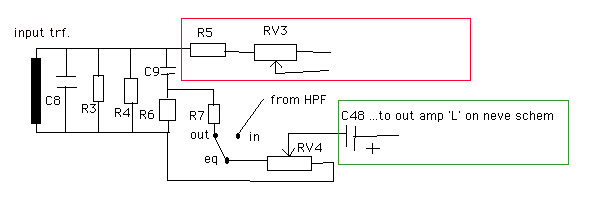
I am now pretty sure that I have an error right after the input transformer. Because: with out+ (of the input tran) connected to the pcb I have the tinny sound on the primary AND secondary of said input transformer, with that node disconnected I have normal sound on both sides (=> transformer seems fine). It seems I have an impedance problem or some sort of severe high pass filter on the secondary of the input transformer. (would that sorta thing also affect the primary side of an input transformer?)

Looking at the schematic there seem to be quite a lot of paths between the two nodes of the secondary winding (the lower one also being signal ground, AFAI understand) I am especially puzzled by R3 and R4 in parallel...is this to get a particular value?

Anyway, good to have you back, peter, and would love to see your abortion of a schematic, to compare and contrast with my reverse engineered abomination. :D

ETA: one more question, what's the jumper between the OT and the word 'london' for?
 

Latest posts

Back
Top