EQN build thread

GroupDIY Audio Forum

Help Support GroupDIY Audio Forum:

This site may earn a commission from merchant affiliate links, including eBay, Amazon, and others.
Thanks Dr Gris!

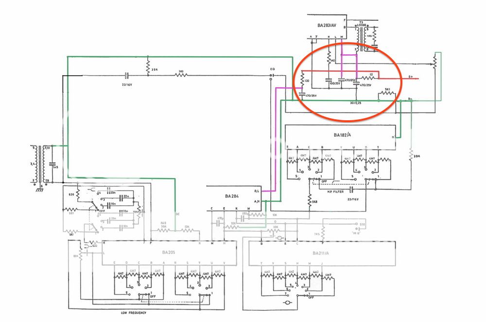
OMG! I accidentally removed C12 and now I can't re-solder it :'( there is nothing for soldering the legs of 470uf ... any idea can safe me?

thanks


Dr Gris said:
Hmmm....if I understand you correctly, you have cut off the last two pins that sat together
after the "notch" in the connector that goes into the Edac connector in the rack?
Those last two pins are for +24V DC (pin 17) and -24V DC (pin 18).
Looking at your pic, those are the ones you cut ( not pin 16 and 17)

You can still make the module work on +/- 16V in the 51X rack.
Pin 12 is + 16V DC and pin 14 is -16V DC. The last three gold plated pins in your pic is pin 12,13,14.
So you don't have to worry about that you have cut the last two pins :)

But what you have to do is to put back the components you took away to make it work again.
All those parts labeled "not needed for 51X" still has to be there.
And thats because you took the last two pins away.
" not needed for 51X" means you run it from the last pins (24V).

I hope I make sense.

Don't give up, and best of luck, I love my EQN's!!
//Magnus
 
jandoste said:
Thanks Dr Gris!

OMG! I accidentally removed C12 and now I can't re-solder it :'( there is nothing for soldering the legs of 470uf ... any idea can safe me?

thanks
[/quote]

C12 is a small 1uF film cap in the filter section. Do you mean C1 and C2 (elyt 470uF)
close to the last pins? Can you take another pic of what you mean?

I have those caps (470 uF 25V electrolyt) as leftovers from the kit from Colin as I didn't
put them in, felt bold in going 24V only 8)
Use some solder wick to clean up the holes in the PCB where they once were,
and I can send you mine for free in an envelope if you need them  :)

Regards
Magnus
 
Thanks!
I meant there is nothing on the BCP :(


Dr Gris said:
C12 is a small 1uF film cap in the filter section. Do you mean C1 and C2 (elyt 470uF)
close to the last pins? Can you take another pic of what you mean?

I have those caps (470 uF 25V electrolyt) as leftovers from the kit from Colin as I didn't
put them in, felt bold in going 24V only 8)
Use some solder wick to clean up the holes in the PCB where they once were,
and I can send you mine for free in an envelope if you need them  :)

Regards
Magnus
 

Attachments

  • photo.JPG
    photo.JPG
    113.3 KB
Ok, I'm not that experienced but I have been forced to remove parts I've put in wrong
and it has looked like that afterwards, but it worked to solder again.
Check the board for continuity where you should have it so that the traces are good,
and try to solder again.

I' m sorry I don't have any more suggestions.
Let me know if you need caps.

Best
Magnus
 
Thanks Magnus! I think I won't need the cap but it was so kind...

Please someone can tell me which 470uf is the C2 on the schema? because I need to solder contact its leg but where I cannot find :)

Thanks


Dr Gris said:
I' m sorry I don't have any more suggestions.
Let me know if you need caps.

Best
Magnus
 
Just follow trace on the PCB and you'll find wich one it is and where the trace has to go for proper contact.
Too bad you lifted an electrolyic cap pad, a ceramic wouldn't need to airwire it (going from your pic)but lifting solo pads can happen easily...
 
And Peters PCBs are a little sensitive... speaking of forcing components of their holes and removing the solder. Thats why I bought a reworking station with a vacuum desoldering iron! Happend to me at least three times building 4 EQNs until now. But you learn how to work around and to be more careful soldering and desoldering those PCBs.
A quick and dirty solution is cutting of the components, leaving the components leads in their holes and soldering to the remaining leads. Of course thats a little problematic with radial Elcos.

Cheers.
 
Thanks Tony!

I think I found it but I want to be sure ::)
So leg 1(+) goes to pin 8
leg 2 (- ) = L2 ?

Is that right?

Thanks


zayance said:
Just follow trace on the PCB and you'll find wich one it is and where the trace has to go for proper contact.
Too bad you lifted an electrolyic cap pad, a ceramic wouldn't need to airwire it (going from your pic)but lifting solo pads can happen easily...
 
Jandoste,

Basically you have to rewire as the trace that is connected to the pad you lifted, since you can't make sure that adding solder on a lifted pad will still make a nice connection in the "plated hole" and so the other side pad.
So just take a black marker pen, and put a point on the pad where the wire should go (looking at the trace destination top side of PCB), and hardwire the lifted pad (cap leg) there, done deal.
Can't tell you yes or no for your previous question ;)
 
Thanks Tony!

I have soldered the cap and my problem  not solved... I think my problem is on AMP(small PCB) and the AMP side has anything 0V! is it wrong no? and the input tranx is the same; 0V! I also changed Lambda DC's voltages is ok 16V and 9V! after the Lambda DC, I don't get any Voltage! 0V-0V-OV and sadly I can't find the problem  :'(

Thanks
 
Hey,

I'm searching the problem but i didn't find it yet! that maybe because of C61/C5/C6 I'm having this problem? I'm measuring them and C5 is 0V but the second build that it works has 24V... please tell me something :'(

Thanks
 
Can't tell Jandoste, I don't have your modules in front of me, and i'm not in front of mine.

It's hard to help someone with the distance jandoste, and solving problems as you may know can be complicated.
Assembling is always easier of course, but that's not electronics and DIY...
I understand that you fried the module when inserting it in the rack, so if after replacement of the "visually" defect parts nothing changed, than this means that something else is fried (obviously) and the only person that can find that out is you, you have a DMM tester, and I guess a lab PSU maybe? Good that you have a working module, that helps as well.
Going with the schematic first thing would be to see if the Power rails are feeding parts of the circuit etc....
Testing diodes, transistors with your DMM etc... Etc....
Finding the fault can be hard and takes time, but that's part of the deal, I wasted a LOT of time trying to solve issues, sometimes you get things quick and you're happy, and sometimes it's a PITA.
Cheer up, and get things Rollin, after all these kits you should be able to find the fault.
Write down what seems to be looking good and what's not to keep track, because sometimes it's good to take a break and get back to it so.....
 
Finally getting around to putting together my EQN's. It only took me about 4 years to get started!

I thought I had a bunch of BC184c's laying around but apparently I haven't a clue where they are. I do have a bunch of MPSA18's and BC550c's laying around. I'm leaning towards using the MSPSA18's (mounted backwards for pin compatibility). Is there any reason to choose one over the other to substitute for the 184c's?

Can't wait to hear these things!
 
Back
Top