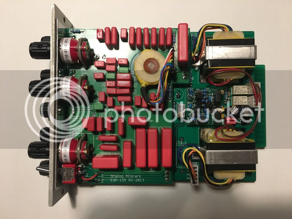
EQP-1S5 500 series PULTEC ---- HELP/BUILD thread

GroupDIY Audio Forum

Help Support GroupDIY Audio Forum:

This site may earn a commission from merchant affiliate links, including eBay, Amazon, and others.
Hey y'all, close to finishing up this build but ran into this issue...

I don't have clearance for the inductor connector. What did I do wrong?

34iq0dc.jpg

eq5q4n.jpg
 
sws2h said:
Hey y'all, close to finishing up this build but ran into this issue...

I don't have clearance for the inductor connector. What did I do wrong?

34iq0dc.jpg

eq5q4n.jpg
Hi,  the inductor is mounted on top with the rest of the components. Be careful removing the header so you don't lift any pads.  Check them after the work is done to be safe.

Good luck!
 
:p I misread the instructions.

I was able to get the header out without lifting the pads.

I was able to get the header out and flipped around.

One last question, I believe I was short 1 plastic retaining washer. I used four for the transformer brackets, but that left out the one for this step for the inductor post: Long screw from the bottom of the sled, then the metal spacer from the top, and then one of the plastic retaining washers (PRW) to hold it all in place.

It's all secure, but is the metal spacer touching the circuit board = trouble? Also, the inductor can be wiggled around, is it suppose to be held down tightly? I don't think I can tighten the screw/washer assembly down any more.

Thanks for your help, real close!

Sean

***Also what is the function/benefit/purpose for the optional polystyrene capacitors?
 
Hi, I've been traveling the past few days, apologies for the delay.  Good job reversing the header, we're always updating the build doc based on people's experiences, so I'll add a note about the inductor placement to avoid confusion.

As for the retaining washer, you're OK without it, those things are so small and light they tend to get lost easily. Probably jumped out of the box before we shipped it!  It's ok if the standoff touches the bottom of the PCB, there are no traces nearby so it can't hurt anything.

The inductor is a bit "wiggly" when screwed down. 

Seems like you're pretty close.  Once you're done, take your time and test the opamp PCB before you solder the two boards together and you should be good to go!

good luck!
 
Figured out the problem (forgot to jumper the optional capacitor) Now everything works and sounds good except 22K high frequencies is just a full range boost. Maybe a shorted leg on the pot?

Also, when adjusting the boost, attenuation, and bandwidth knobs I often get a static sound (I have a similar issue with my FET/500 Rev A and Rev D)
 
sws2h said:
...Now everything works and sounds good except 22K high frequencies is just a full range boost. Maybe a shorted leg on the pot?
If the other frequencies are working OK, then the problem is in the last position of the high-boost switch. The pot should be OK.  Sounds like a short, try using a continuity checker to see what's going on. 

Also, when adjusting the boost, attenuation, and bandwidth knobs I often get a static sound (I have a similar issue with my FET/500 Rev A and Rev D)
This one is a bit trickier. I've never experienced this. Normally a scratchy pot means there is DC in the circuit, though I can't see how it would get in there.  Do you see any DC on those pots when the unit is turned on?

good luck
 
Hey all-

  Thanks in advance for the help.  I'm having a bit of trouble getting mine to work. 

Currently I'm testing the amp board with the filter board removed and the jumpers in place as per the troubleshooting guide.  It passes signal, but the signal is very distorted and has no low end.  So far I've tried two known working DOA's, (gar2520 and gar1731), checked voltages at the op amp sockets, double checked component values and orientation,  reflowed every joint, scrubbed with alcohol, checked that there is a connection between a ground point on the board and the ground pin on the edge connector, measured both transformers resistance (brown to red 71.7, orange to blue 71.1, orange to yellow 11.7, green to blue  14.5) and run a square wav through it and scoped it to see where the signal goes bad.  The square wav appears to be fine going into the input transformer (Brown lead) but is very distorted on the way out (Orange Lead).  Which makes me wonder about the transformer.  Those measurements are about 10 ohms higher than what they should be based on the help thread.

Also, I've had a hard time finding a definitve answer in the help thread about whether R9 and C34 should be jumpered if there's no component in place.  My CF cap is in place and C_DC is jumpered.  R9 and C34 are not jumpered.

thanks!

-mike
 
Hi,

I just measured a brand new transformer and got almost exactly the same DCR measurements.  I would guess the transformers are OK, but check to make sure you don't have any broken connections at the molex, and that you have them plugged into the right spot (the 3 pin molex connectors should cross over one another). These transformers can take a lot of signal, but even so, make sure you aren't overloading them.  Try running a lower level through them and see what happens. 

R9 on the amp PCB and C34 on the filter PCB should be left open, nothing at all in those positions.

Cf is optional, and C_DC should be jumpered or have a 100uF cap in it if your opamp has high DC offset (not normally required for 2520 or 1731 opamps, but, to be on the safe side, you may want to check if you have DC at the output of your opamp).

Good luck!
 
Thanks for the reply Mitsos. 

I resoldered all the connections and confirmed that I have the transformers plugged in correctly.  I also tried lowering the input signal, no luck.  I've been checking the signal with the scope directly at the plugs on the tranny, so I know it's not the pins on the board. 

An interesting new find, If I use a sin generator and the scope I can get sin waves of 20hz on up to 3k show up at the brown lead of the input tranny.  Once I move the probe to the orange lead on the other side of the tranny the amplitude of anything below 400hz is super low, gradually growing until the higher frequencies are very loud, which correlates with how audio sounds going through it, no bass and distorted highs.  Since I'm measuring right at the wire ends where they meet the molex I feel like there must be something going on inside the tranny. 

Any further thoughts anyone?  Thanks for the help.

-mike
 
gunner666 said:
Thanks for the reply Mitsos. 

I resoldered all the connections and confirmed that I have the transformers plugged in correctly.  I also tried lowering the input signal, no luck.  I've been checking the signal with the scope directly at the plugs on the tranny, so I know it's not the pins on the board. 

An interesting new find, If I use a sin generator and the scope I can get sin waves of 20hz on up to 3k show up at the brown lead of the input tranny.  Once I move the probe to the orange lead on the other side of the tranny the amplitude of anything below 400hz is super low, gradually growing until the higher frequencies are very loud, which correlates with how audio sounds going through it, no bass and distorted highs.  Since I'm measuring right at the wire ends where they meet the molex I feel like there must be something going on inside the tranny. 

Any further thoughts anyone?  Thanks for the help.

-mike
Hi Mike,

I just ran a 1V signal through one here and got no real signal loss all the way down to 25Hz or so.  At all times though it was a clean sine wave.  Sorry, but I have no idea what the problem is with your transformer, but send us an email and we'll get another one out to you.  I'd like to get the faulty one back, please, so we can take it apart and see if it was a manufacturing error or shipping damage, etc.  Sorry for the inconvenience.

cheers!

 
Hi all-

  Please see my earlier posts about distortion and low frequency loss.  It turns out it was an opamp problem.  I tried a known working GAR2520 and a GAR1731 and they both exhibited the same issue so I spent a lot of hours looking elsewhere in the circuit.  Turns out it didn't like EITHER of my op amps.  Hopefully I can save someone else the hours I spent.  If you're using a GARxxxx try something else before you spend a lot of time looking for a problem that's not there.

thanks to Neils for his assistance and a great kit.

-mike
 
Yes, most 2520 opamps should work just fine in the circuit.  I know of a pair locally that IIRC have GAR2520s, another with our 2520s and have heard from people using Purples, PPA (992 and some others), Mike Fatom 2520s and JLM99V. 

With the JLM99V you must install the extra electrolytic in the feedback path due to the opamps high DC offset, with the others you can just put install a jumper.
 
I have GAR 2520s in mine too,they are working fine for years now.
Did you build your DOAs yourself?
And how did you find it out it was the issue?
Do the "....known as working..."  ones work in any other build?


@Mitsos:Hi Dimitri,any news on the meq5  (damn close to christmas now ;) )


Best regards,


Udo.


Is it out of line to ask for the schematic? Being that it's the same (except for the extra freq points) as the Pultec version with 2520 amp? The reason I ask is that Pultec schematic seems to be as rare as hen's teeth. I had one that is supposed to be a redraw at one point, but now I've lost it. Doh.

Can someone confirm that the one that Joe Malone posted earlier (first page) is correct? (minus his modifications for the 99V opamp)

 
Hi all!

Just recently built an EQ-1S5, super happy about it but i just discovered that something is wrong with the lowband attenuation. Say i want to attenuate 220hz, the signal drops considerably by just moving the attenuation knob just a little bit. On full attenuation it´s like a lowpass filter. Any help would be much appreciated!

Thanks a lot -cheers

Sent a acoustic guitarloop through the unit to demonstrate the issue (attenuating 220hz), first bar no attenuation, second att-knob at 9, third at 12, forth at 15, last full on. Here´s the link https://www.dropbox.com/s/2prxj3bgbemz6xi/aa-attentuator.mp3?dl=0

IMG_0215_zpsw5v9yxec.jpg
 
All of the other filter bands are behaving correctly?
Are you sure that the correct pots are in the correct positions?
Are both units behaving the same way?
 
Thanks for replying!

Yes, everything else on the unit is fine! All pots are in correct positions! Only got this one unit!
 
I thought everything else was fine but the boost on the lowend-filter is also very aggressive! Did a quick filter sweep on 220hz, first boost then attenuate! https://www.dropbox.com/s/no8q0zbkc4ydvpm/aa-sweep-220-boost-attenuate.mp3?dl=0

Thanks again!
 
Possibly a shorted pin on the switch? Take a close look at the solder joints on the Grayhill switch
If you can run any type of analyzer on it to see what it is actually doing, that would help as it is not clear from the audio you post that is misbehaving.
There are frequency response plots posted earlier in the thread...
 

Latest posts

Back
Top