mitsos
Well-known member
- Joined
- May 4, 2007
- Messages
- 2,886
Good to hear that's sorted. See below for LED info.Monoklang said:Thanks! Yes I took some tape, and now they sits perfectly. But now when I put the module into my 51x rack to calibrate it, the LED doesn't seem to work. How can I test if this is broken?
Well, you should only leave out R9... not any other resistors. R5 should not affect signal coming in or out, but for sure r6 affects the LED, it's the current limiting resistor, without it the LED circuit is broken.I left out the R5-R6 as you suggested. First I thought I wired the on/off switch wrong, and switched but still no light. And no signal
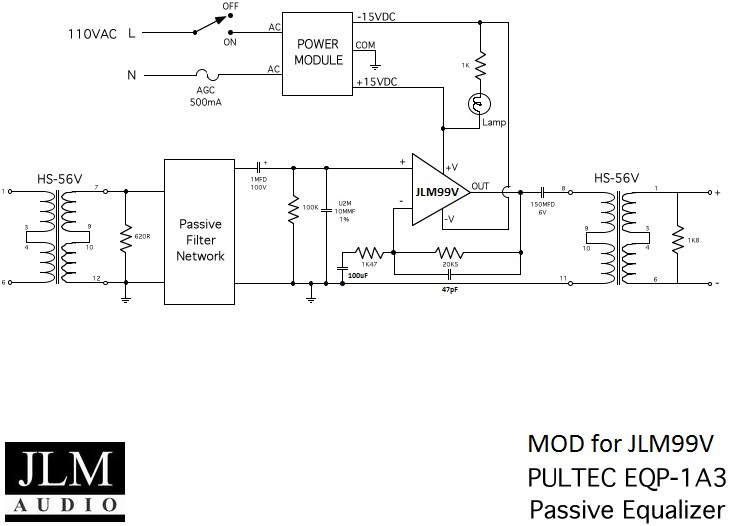
To check for signal, you can probe at the topmost header near the input trafo (module held vertically). That's the secondary of the input trafo, signal here confirms your relays and input trafo are wired/working properly. Then check the third header. That's the output of the filter, you should see signal (about 21.6 dB lower than at pin 1). If no signal then you need to check the filter PCB for shorts to ground. If this is OK, then probe around C47, the output cap, that will show problems in your opamp circuit, and finally the output pins of the card edge to check for issues with the output trafo.
Don't worry it's not only you... I find its always the easy ones that give me problems!It's so typical, I thought this build was really a quick one, with no strange things, just easy enough for me.
Any clues?
Best regards
John


![Soldering Iron Kit, 120W LED Digital Advanced Solder Iron Soldering Gun kit, 110V Welding Tools, Smart Temperature Control [356℉-932℉], Extra 5pcs Tips, Auto Sleep, Temp Calibration, Orange](https://m.media-amazon.com/images/I/51sFKu9SdeL._SL500_.jpg)


