Triode-Joe said:
I have a couple Siemens u274s that I use to give "character" to drums, electric piano and Hammond organ.
Awesome. Interestingly I actually have two originals I got off of ebay. But I still haven't fired them up yet. I actually bought them as reference for this project. I definitely want to fire them up at some point soon. But I almost feel this project now has a bit of a life of it's own.
Triode-Joe said:
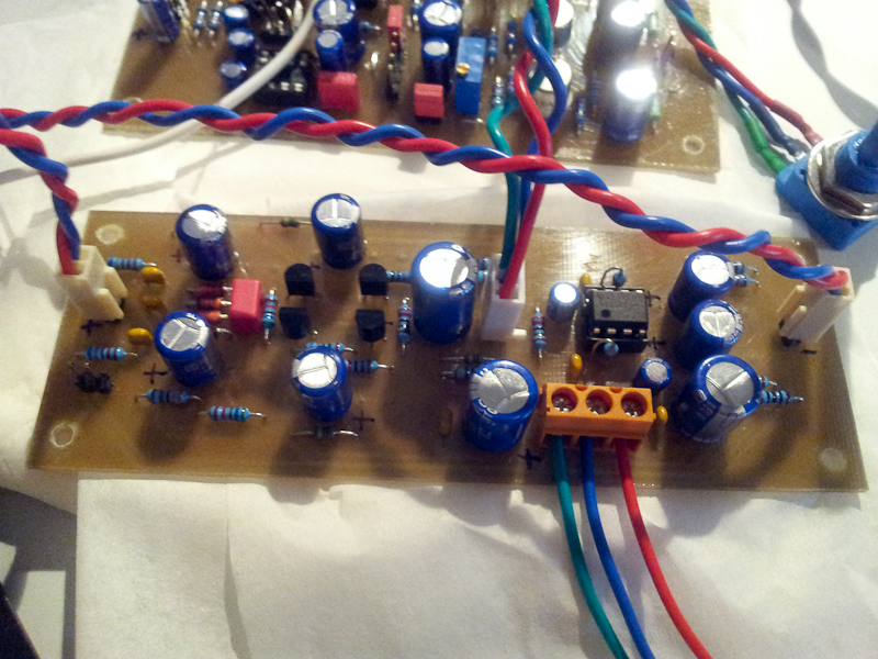
It looks like your main work here is on the diode bridge and associated caps
Yes and no. There was an equal amount of work on removing the input and output transformers for ease of construction/parts availability and size/weight.
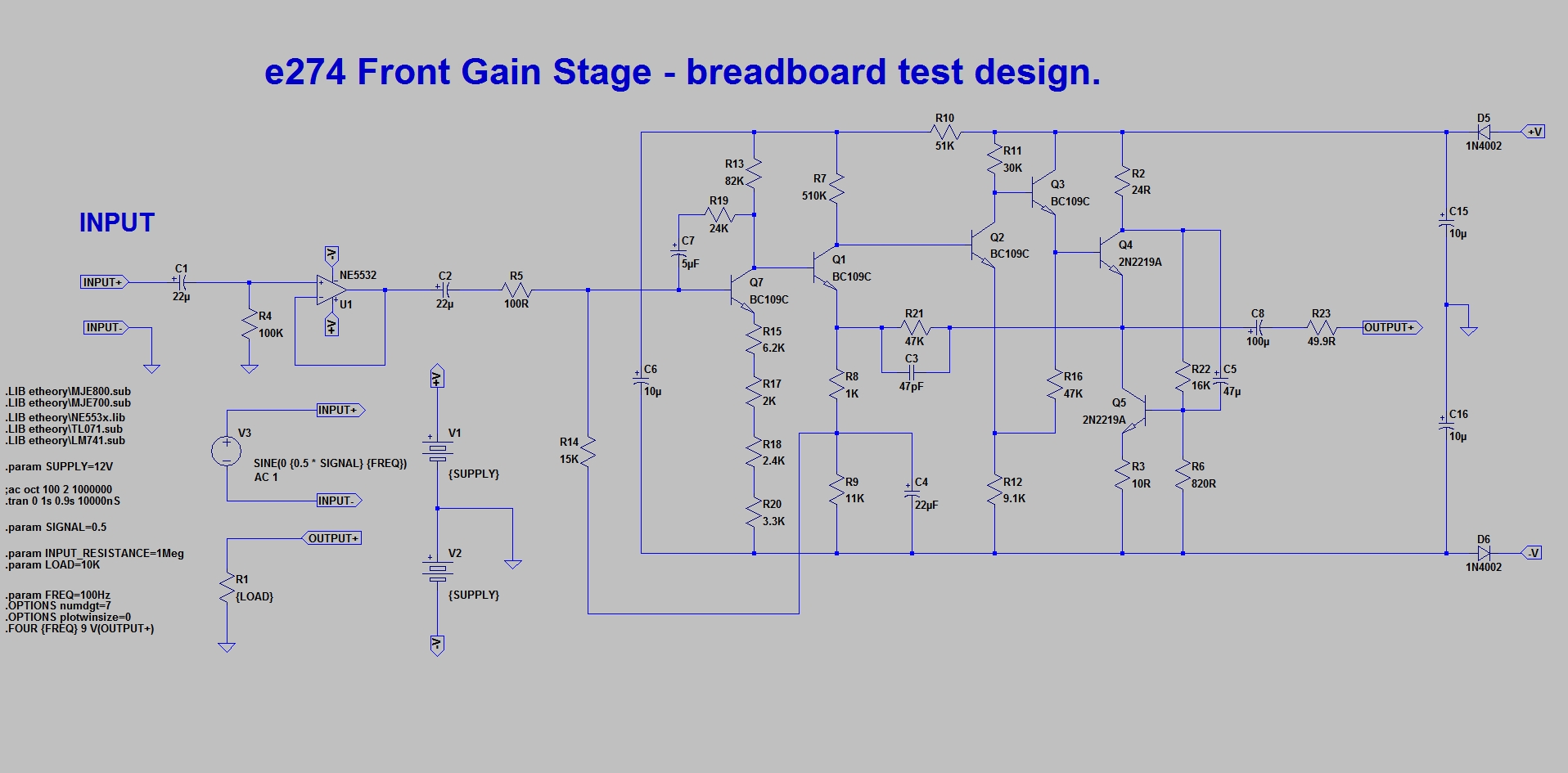
I also modified the audio circuit for different and higher power rails for more headroom, much lower power consumption and the option of different modern equivalent transistors such as BC550 + BD139 etc.
Triode-Joe said:
I have always considered the U274 to be a one trick pony, but as I read through this thread, I wonder if your work could be applied backwards to the U274?
It might be a tiny bit messy but absolutely. That should definitely be possible.
Triode-Joe said:
The idea of a simple method of adding variable comp ratio, side chain filter and simple attack/release times makes me wonder if a new daughter board might make the original modules far more useful. I would appreciate any thoughts.
I'd be happy to provide some mod ideas and how to do them. I'll make sure to post that here + some proper diagrams over the new few weeks. But that should be no issue, aside from snipping wires in your compressor a little bit.
Just so you know, here are a few pointers you could use for the original:
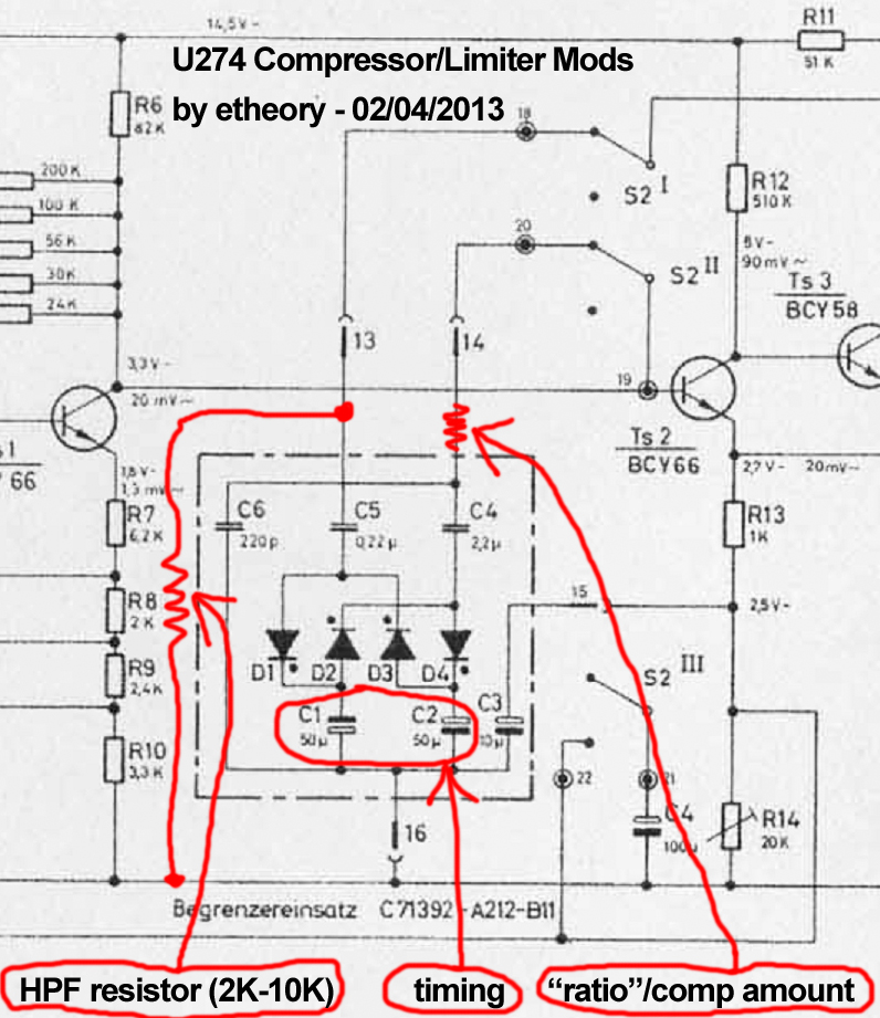
HPF: The filter is a high pass filter based around running a resistor between 2K and 10K from the point between the diode bridge and the 0.22uF side-chain feedback capacitor to ground. I'll draw you a diagram when I get home, but it should be obvious from the schematic of the original (on Kubarth's site) where that point is. That turns the side-chain feedback path into a simple RC filter. It actually works a lot better than you might expect ;-) 10K is around 72Hz and 2K around 361Hz, with other values filling the space between. 10K there makes a huge difference to the clarity of compression from the original.
TIMING: I haven't been clever enough yet to separate attack and release, but simply switching out the two 50uF caps for 10uF, 22uF, 33uF, 47uF and 100uF should provide a range of different useful timing constants. Careful with oscillation if the cap is too low however. This depends a lot on the diodes you have.
RATIO: Not sure if ratio or "compression amount" is a better name for this, but a resistor between the Ts1/Ts2 connection and the 2.2uF capacitor will reduce the amount that the diode bridge can affect gain. Hence driving the diode bridge hard will have less effect the higher this resistor is. Values between 0R and 100K give you approx 1:Max to 1:1 compression. The lower the resistance here, the higher the "ratio".
That's all I have so far. But they do all work. You will definitely have to experiment however.
(edit: this edited image might make all the text clearer - If you want me to take this down Kubarth, just lemme know, sorry if it's cheeky to crop an image of yours directly, but I thought this would make things infinitely clearer)
On another tip.
If you want to improve the high frequency response of the original, swap C1 from 5uF to 22uF and drop the 220pF C6 entirely. This gives a tad more high end when under compression.
That, along with the HPF resistor brightens up things rather nicely and still retains a lot of the original compression action.
Also remember a feedback compressor is really just a well-adjusted oscillator. So if any modifications create a high frequency oscillation (even when no audio is being processed), it's because your feedback loop is too intense from the output transformer, and through C5. One remedy for this is a resistor between 100R and 6.2K sitting in series with the side-chain feedback path and before C5. This limits the signal passing through the feedback loop, and, hence, reduces, and when high enough eliminates, the chances of oscillation.


") Especially at the risk of someone else building a horrible design. It seems from my current analysis that what I've done is accidentally produce positive feedback around the input stage, completely accidentally, which of course will make it squeal. So time to correct that....
Especially at the risk of someone else building a horrible design. It seems from my current analysis that what I've done is accidentally produce positive feedback around the input stage, completely accidentally, which of course will make it squeal. So time to correct that....


![Soldering Iron Kit, 120W LED Digital Advanced Solder Iron Soldering Gun kit, 110V Welding Tools, Smart Temperature Control [356℉-932℉], Extra 5pcs Tips, Auto Sleep, Temp Calibration, Orange](https://m.media-amazon.com/images/I/51sFKu9SdeL._SL500_.jpg)