Kingston said:
Thanks for posting these.
You are more than welcome.
Kingston said:
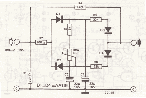
Have you scoped or simulated the effects of these diodes much?
In a lot of detail, but simulation difference is nothing like what is occurring in the real world situation.
The simulations don't show the type of distortion you get when the diodes begin to conduct out of their ohmic region (where the compressor starts generating nasty distortion, which starts at a higher signal level for a silicon than zener/schottky/germanium, hence the 1N4148 can take more input signal more cleanly).
Kingston said:
The only difference, besides forward voltage drop, would be the reverse breakdown voltage spike. And that's so fast it shouldn't have any audible effect.
The first diode sounds like it's distorting more than 1N4148. Might be as simple as a level difference from forward voltage drop of the diodes. And since it's in a CV loop call it "threshold".
Well there is one thing that occurs that means the circuit can't be the same for different diodes.
The schottky basically conducts for "all" CV levels - it is so sensitive, that unless I have at LEAST 6.2K in the feedback loop to reduce the current in the feedback loop, the whole amp oscillates at high frequency around the CV feedback loop, due to the direct path and the lack of resistance of the Schottky array.
The 1N4148 doesn't do this due to it's higher signal level requirement to start conducting in the ohmic region. In fact, you don't need any resistance at all in the feedback loop with it, and it's higher signal level handling also makes a difference.
Kingston said:
I would recommend simulating this diode configuration in isolation with real world input level. No point in complicating this with listening tests. You could then perhaps move into active biasing tricks where you can play with the forward voltage drop, no longer limited to diode selection.
Well, at this point, I think for this particular circuit I've messed with it about as much as I can be bothered messing with it ;-)
The 1N4148 is also giving me a much higher compression ratio also, which is great, and doesn't suffer from any oscillation issues like the lower voltage diodes can, so it seems like a more sure-fire bet to put in a kit for other people, as it's much more likely to give consistent behavior. However you could also put a 10K trimmer in the CV feedback loop to trim out any high frequency oscillation that might occur due to your particular choice of diode.
So I think I'll clean up the design now, re-do the circuit layout and build another proto over the weekend.
Thanks so much everyone for your help. I'm not ignoring the feedback, it's more that I think it's time to wrap this one up and move on!
However, I will be revisiting the diode topology very soon in a couple of different ways.
Controls will be:
1.) Input volume (after debalancing NE5532)
2.) Output gain (NE5532 balancing stage)
3.) Passive HPF control (12 position rotary switch)
4.) Ratio (12 position rotary switch)
5.) Release (12 position rotary switch)
6.) Slow and Fast timing (no separate attack control) - 2 or 3 position switch, up to you.
7.) Compressor On/Off (leaving you with just an amp with about 48dB gain max, end to end).


![Soldering Iron Kit, 120W LED Digital Advanced Solder Iron Soldering Gun kit, 110V Welding Tools, Smart Temperature Control [356℉-932℉], Extra 5pcs Tips, Auto Sleep, Temp Calibration, Orange](https://m.media-amazon.com/images/I/51sFKu9SdeL._SL500_.jpg)


