External DC Power Supply System?

GroupDIY Audio Forum

Help Support GroupDIY Audio Forum:

This site may earn a commission from merchant affiliate links, including eBay, Amazon, and others.

ioplex

Well-known member
Joined
Apr 3, 2013
Messages
48
I would like to create an external power supply (rack mount probably) with multiple outputs for powering multiple pieces of gear with up to 3-4 voltages on each output. This would make it easier to build new projects quickly and, in theory, it should be quieter.

I just need to decide on connectors and cable. I reason I need probably at least 6 conductors:

1 shield ground (could be an uninsulated "drain" wire)
2 signal ground
3 power ground
4 voltage 1
5 voltage 2
6 voltage 3

This gives me 3 grounds and 3 voltages but the pins would not have to be assigned specifically. Each output would just be wired as necessary for a particular piece of gear. So one output might be shield gnd, signal gnd, power gnd, +15, -15, +48 and another might be shield gnd, signal gnd, power gnd, digital gnd, +24, +5. And so on.

Current would not be more than what a discrete op amp might put into a 600 ohm load. So 20 AWG conductors would be fine.

Can someone recommend connectors / cables suitable for this project?

Do you see any problems with this scheme?

Comments?
 
I would recommend Ampex CPC series connectors. They are not expensive, they have various numbers of ways, they use crimp pins that take 20 gauge wire and, most importantly, they are round so making holes in panels for them is relatively easy.

Cheers

Ian
 
A typical problem(?) with external DC power supplies is that the DCR of any connecting cables will introduce voltage drops. This can be modest for low power applications.  For higher power I preferred to use pre-regulation in the external PS and then performed final regulation at the final destination. 

I designed one common rack mount power supply to power multiple rack mount products.  While DC would have been cheaper, I decided to use a transformer with a half dozen isolated secondary windings so I could provide power that each unit could draw as they wanted, all without a common ground connection. The AC power was delivered via common 2-pin connectors like used on wall wart PS.

Distributing DC across several chassis with a common ground can be done but you will need to properly keep all audio I/O differential wrt the single common ground voltage (0V).

JR
 
ruffrecords said:
I would recommend Ampex CPC series connectors. They are not expensive, they have various numbers of ways, they use crimp pins that take 20 gauge wire and, most importantly, they are round so making holes in panels for them is relatively easy.
Yes! CPC looks perfect.

But can you recommend a particular manufacturer / sub-series? Looking at Mouser / Digikey / Newark / Allied, there are literally hundreds to choose from. Is there a particular variety of CPC connector that is popular or is there some parameter like size that I can use to narrow down the selection?

I know nothing about these connectors. I suppose I could just buy 3-4 different ones and then decide.
 
JohnRoberts said:
Distributing DC across several chassis with a common ground can be done but you will need to properly keep all audio I/O differential wrt the single common ground voltage (0V).
Just to be clear, there would be no signal on the cables. They would just be for power.

EDIT:

Actually I didn't quite understand your comment but now I think I do.

Having separate grounds doesn't really solve the problem of noise getting into the signal ground.

For example, lets say there is a "power ground" wire that is being used with some relays and as the relays switch, there are significant changes in current on that wire. Even though the power ground is separate from the "signal ground", it would be running alongside it and so the changes in current on the power ground could (and probably would) electromagnetically induce currents in the signal ground. And it might be worse if the cable were coiled in a loop. And making the signal ground a separate piece of coax doesn't help because the problem is electromagnetic and not electrostatic.

However, if there is sufficient filtering at the remote ends, would that not smooth out currents on the grounds?

I'm pretty good with LTspice but I'm not an Engineer. Anyone have a good idea of how to model EMI in long parallel runs of wire?
 
Just to be clear "ground" is a connection, not a voltage. It can only be 0V at one point and any currents flowing in that ground path will introduce voltage drops.

Differentially handling audio as separate audio + and audio - components can ignore small differences in ground.

JR
 
ioplex said:
Anyone have a good idea of how to model EMI in long parallel runs of wire?
You don't need that.
Just use Ohm's law. Lets' say you engage a realay that draws 40mA. A 5m length of AWG20 measures 0.16 ohm. The voltage developed in the conductor will be 6.4 mV. That means the " "ground" " of the unit where the relay is will move by 6.4 mV. If this " "ground" " is also the audio "ground", this "ground will move by 6.4 mV compared to any other unit that is referenced to something else. This common-modevoltage will appear on the signal if these two units are connected together. If the connection is balanced, it will be cancelled. If the connection is unbalanced, it will appear in full, superimposed on the signal.
I've given the example of a sudden change in DC current, but that would be exactly the same for any AC signal that would develop in the 0V conductor.
 
ioplex said:
ruffrecords said:
I would recommend Ampex CPC series connectors. They are not expensive, they have various numbers of ways, they use crimp pins that take 20 gauge wire and, most importantly, they are round so making holes in panels for them is relatively easy.
Yes! CPC looks perfect.

But can you recommend a particular manufacturer / sub-series? Looking at Mouser / Digikey / Newark / Allied, there are literally hundreds to choose from. Is there a particular variety of CPC connector that is popular or is there some parameter like size that I can use to narrow down the selection?

I know nothing about these connectors. I suppose I could just buy 3-4 different ones and then decide.

That's the only problem with the CPC range - they are just so flexible. I have tried to standardise on a nine pin connector as that gives me 8 pairs and an overall screen. I don't remember of hand which series I use.

Cheers

Ian
 
i used an octal type connector like a power tube uses, works fine, did not need 3 grounds, just one, so power goes ground, 6 v-dc for heaters, 12 v-dc for heaters or relays, 24 volts for relays, -24 volts v-dc for transistor dual rail circuits, ad 300 vilts for tube stuff, use a cap at the end of each voltage inside the preamp, compressor, or whatever you power,  yes this will quiet things down quite a bit, no hassling with xfmr placement and all that,
 
ioplex said:
I would like to create an external power supply (rack mount probably) with multiple outputs for powering multiple pieces of gear with up to 3-4 voltages on each output. This would make it easier to build new projects quickly and, in theory, it should be quieter.

I just need to decide on connectors and cable. I reason I need probably at least 6 conductors:

1 shield ground (could be an uninsulated "drain" wire)
2 signal ground
3 power ground
4 voltage 1
5 voltage 2
6 voltage 3

This gives me 3 grounds and 3 voltages but the pins would not have to be assigned specifically. Each output would just be wired as necessary for a particular piece of gear. So one output might be shield gnd, signal gnd, power gnd, +15, -15, +48 and another might be shield gnd, signal gnd, power gnd, digital gnd, +24, +5. And so on.

What I would do, and what we do at the day job for our power-supply cables, is to have a DC return wire for each supply wire. So if you have four supply rails you have four ground wires.  You want this because Electronics 101 tells you that current out has to have a matching current back to the source.

And I am with JR on the pre-regulation in the external supply with final point-of-load regulation at the system.  While I am sure that you can calculate the IR drop for a given fixed length of cable and "wag" it,  remember that the IR drop will be a function of dynamic load. I suppose that most op-amp circuits have decent-enough PSRR to make that less interesting, but, hey, you never know.
 
Why not use XLR connectors? A lot of pro audio supplies use them. They make 5 pin and the shield can just be the housing body. You can also tie signal and power grounds at the device and run it back to the supply on a single wire. Then you are down to a 4 pin XLR like Chandler, API, BAE, etc.
 
Andy Peters said:
What I would do, and what we do at the day job for our power-supply cables, is to have a DC return wire for each supply wire. So if you have four supply rails you have four ground wires.  You want this because Electronics 101 tells you that current out has to have a matching current back to the source.
It is indeed a most versatile option, that many console manufacturers used as it allowed them to power a number of different mixers with a restricted choice of PSU blocks. It may not be justified for DIY. The problem is that the price of connectors grows drastically with the number of contacts.
And I am with JR on the pre-regulation in the external supply with final point-of-load regulation at the system.  While I am sure that you can calculate the IR drop for a given fixed length of cable and "wag" it,  remember that the IR drop will be a function of dynamic load. I suppose that most op-amp circuits have decent-enough PSRR to make that less interesting, but, hey, you never know.
I have seen many cases where on-site regulation tended to impair performance. That is particularly true in mixers. Most regulators generate rather large noise current; although, in an ideal design, these currents would be restricted to a very small area and not be allowed to pollute other areas, in practice there is most of the times a detrimental effect on noise.
Voltage regulation is not a necessity with most modern designs, that have enough NFB to ensure proper performance and PSRR.
I remember a board that was made by a well-known manufacturer of ENG mixers. It was their first entry in the large mixer market. The mixer was unduly noisy. I traced the problem to the use of LM7824 on each module. I replaced the 7824's with a transistor+zener AND a series resistor then the problem was solved.
It is indeed necessary to distribute only the cleanest possible voltage.
 
john12ax7 said:
Why not use XLR connectors? A lot of pro audio supplies use them. They make 5 pin and the shield can just be the housing body. You can also tie signal and power grounds at the device and run it back to the supply on a single wire. Then you are down to a 4 pin XLR like Chandler, API, BAE, etc.
There are even 7-pin, such as used in the 51X-format; 5 voltages, one common 0V and earth.
 
abbey road d enfer said:
I have seen many cases where on-site regulation tended to impair performance. That is particularly true in mixers. Most regulators generate rather large noise current; although, in an ideal design, these currents would be restricted to a very small area and not be allowed to pollute other areas, in practice there is most of the times a detrimental effect on noise.
Voltage regulation is not a necessity with most modern designs, that have enough NFB to ensure proper performance and PSRR.
I remember a board that was made by a well-known manufacturer of ENG mixers. It was their first entry in the large mixer market. The mixer was unduly noisy. I traced the problem to the use of LM7824 on each module. I replaced the 7824's with a transistor+zener AND a series resistor then the problem was solved.
It is indeed necessary to distribute only the cleanest possible voltage.

I experienced a problem with 3 terminal regulator noise in a large console that was in production and relatively noise free (consoles are never completely noise free) for a couple years.  I isolated the noise in only one vendor's 3 terminal regulators, and when they refused to spec output noise, I black-balled them. Multiple other vendor's 3 terminal regulators were acceptably quiet.

That said I generally agree with Abbey, consoles don't need tight voltage regulation, but when dealing with so many active devices you want to remove all (most) ripple from the PS rails.  When dealing with console noise sources I like to close all the windows I can.

JR
 
I just did a simple test and found that any inductive effect is negligible.

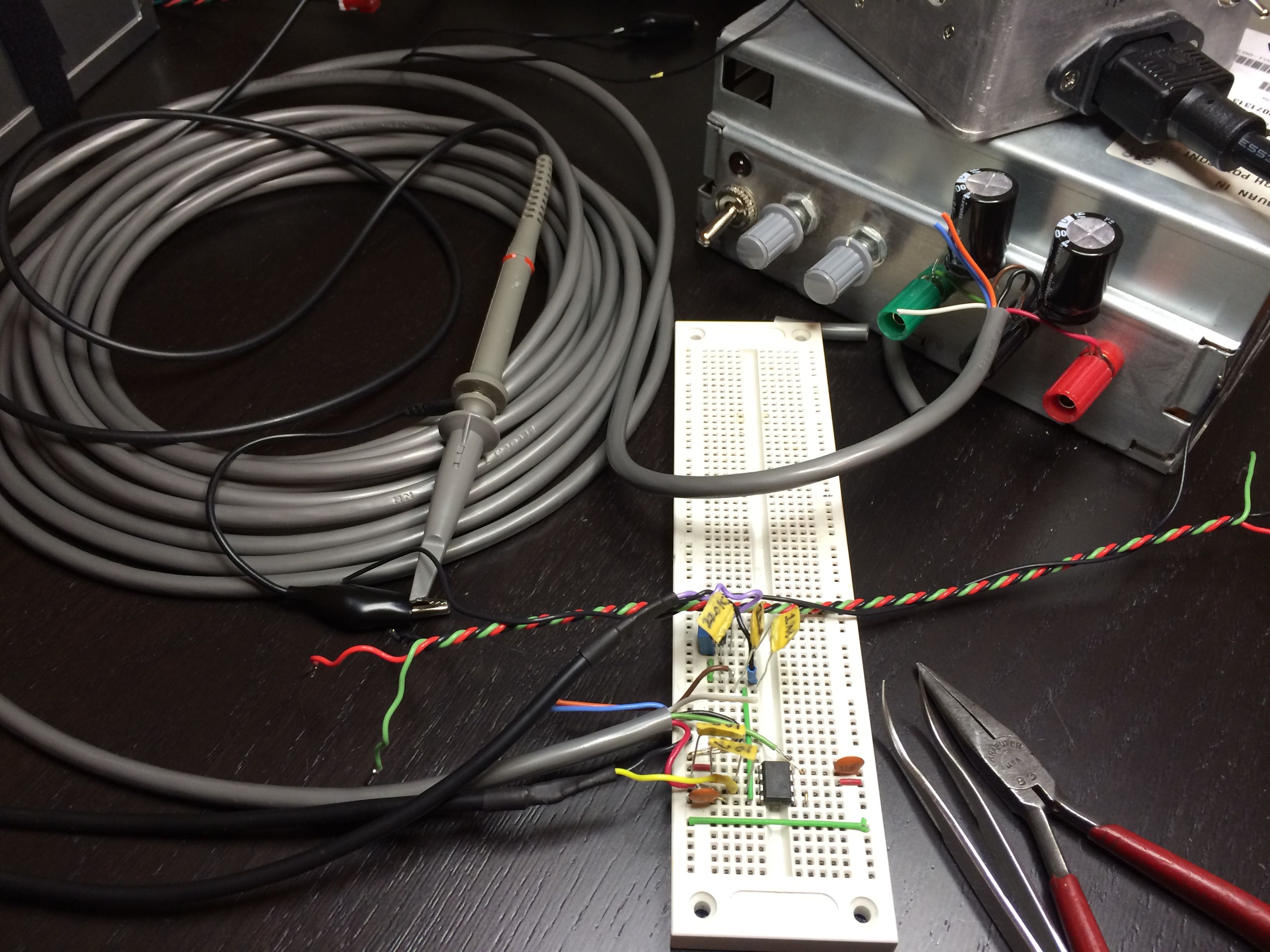
Specifically, I created a simple non-inverting op amp TL082 stage with + grounded and +40 dB of gain. Next to that (but separate), I created a simple Mosfet circuit that would just sink current based on my audio analyzer [1] sine stimulus. I adjusted the stimulus level so that the Mosfet would turn on to the point where it's drain voltage would drop ~8V of a 15V supply across a 220 ohm resistor. So that should be ~36 mA peak. So the analyzer output drives the Mosfet while the input is listening to the op amp and the idea is that if there's any crosstalk, I'll see a peak.

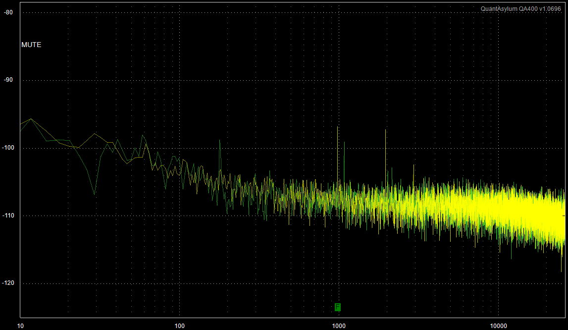
So at first I used relatively short power leads, got a small peak (green trace in the graph below at 1.08kHz) and saved that. I noted at this point that thin breadboard jumper wires were very bad so I used high quality 20 AWG wire with header pins soldered on the end.

Then I inserted 22 ft (6.7 m) of Belden 7 conductor 22 AWG unshielded cable to deliver power to the circuits. At first I connected the Mosfet ground to the op amp ground locally and got a peak +25 dB greater than the "small peak". I noted that it made a significant difference where the ground was connected but the best case was +25 dB.

EW0M0lz.jpg


Finally, I used a separate conductor for the Mosfet ground. So the Mosfet ground and op amp ground used separate conductors that run back over the 22 ft of cable directly to the filter caps on the power supply. This is the yellow trace at 990 Hz:

5rTrn3Q.png


As you can see, the difference between short power wires (green trace at 1.08 kHz) and 20+ ft of 22 AWG conductor with separate grounds (yellow trace at 990 Hz) is only about +2 dB (albeit with a notable 2nd harmonic).

Note that to the peak might look significant but bear in mind the graph is zoomed in on the noise floor. Meaning the peak is only 10 dB above the noise floor of the +40 dB op amp.

I have ordered CPC connectors. I got standard shell size 11-9 pin receptacles, plugs, cable clamps, male and female crimp pins and the insertion tool (see TE Connectivity 206485-1 plug and associated datasheet for compatible parts).

This should make projects a whole lot easier ...

UPDATE:

With a 100 ohm / 100 uF filter separating the Mosfet supply from the op amp supply, there is absolutely no detectable peak at all. I don't suppose this is surprising. But it is a little surprising that it remains true even when using one ground for everything. And I adjusted the Mosfet circuit and increased the stim to dump even more current into the ground. Without the bypass, I completely rebuilt the test circuit twice and even tried adding a 3rd ground conductor for the op amp but I could not best the 10 dB peak.

So I guess the moral of this story is that, in practice, as long as anything that uses a significant amount of power is properly bypassed / buffered, one single ground would be just fine. But knowing that using a separate ground for the "quiet" ground yields a 20+ dB improvement in ground noise, I will probably settle on 3 ground conductors:

1) Shield Ground - for chassis and shields of cables and similar
2) Quiet Ground - for inputs and voltage references and other sources of very small currents
3) Regular Ground - for everything else

This way, I know that if the circuits being powered are not perfect (this is for DIY after all), the extra conductor does add some significant immunity to ground noise.

Note that none of the above has much if anything to do with ground loops. That is an entirely separate issue that has not been tested and ground loops could be a serious issue with such long ground wires. Personally, I have always tried to just used transformers to isolate grounds because there is always some piece of gear that makes things hum without them. Yes, transformers are expensive. But they are foolproof and they provide the best possible performance.

Aside: Although a strong second place to an input transformer are the THAT 1200 Series InGenius ICs. Personally I think that for one-off projects, the time spent on building the extra circuitry is not worth the cost of the transformer.

[1] Quant Asylum QA400 with custom transformer isolated in/out front end.
 
watch out for ground loops if you use more than one wire, you will be defeating the reason for the ext supply in the first place,

as long as the shield, pwr supply and audio grounds are wired good in the mic pre, it should not matter if you route them to the pwr supply with one wire,

 
What do you think about using switching mode power supplies for a pro-quality audio external supply system like this?

f5L5hR6.jpg


I was thinking about putting transformers and rectifier / filter boards in the external supply and then do the filtering and regulating separately in each piece of gear being powered. But I was thinking about how good SMPS are now and had to pause.

SMPS PROS / CONS:

PROS: compact, efficient, they are actually isolated because the output is a transformer, they're cheap, they last forever and they come in a wide variety of voltages that can be wired in series to make a negative voltage (usually).

CONS: generate major EMI, high ripple and when connected to generate a negative voltage the overload circuit protection would be broken.

However, because this would be in an external enclosure, EMI is not really an issue. It would probably be placed on the floor 3-4 feet away from the gear being powered. As for the ripple, it's still simpler and cheaper to just add an LC filter or double regulate if necessary.

Does anyone know anything about these SMPS and can you recommend a model or brand that is known to work well in series to make bipolar voltages?

I was also thinking about getting one of those solid state relay boards on Ebay and then I could use one of the supply cable conductors to control the relay so that the power switch on the front of each piece of gear could turn on / off the AC to each SMPS as necessary.

I'm pretty sure some of the 500 series "Lunchbox" racks actually use switching mode power supplies.
 
Back
Top